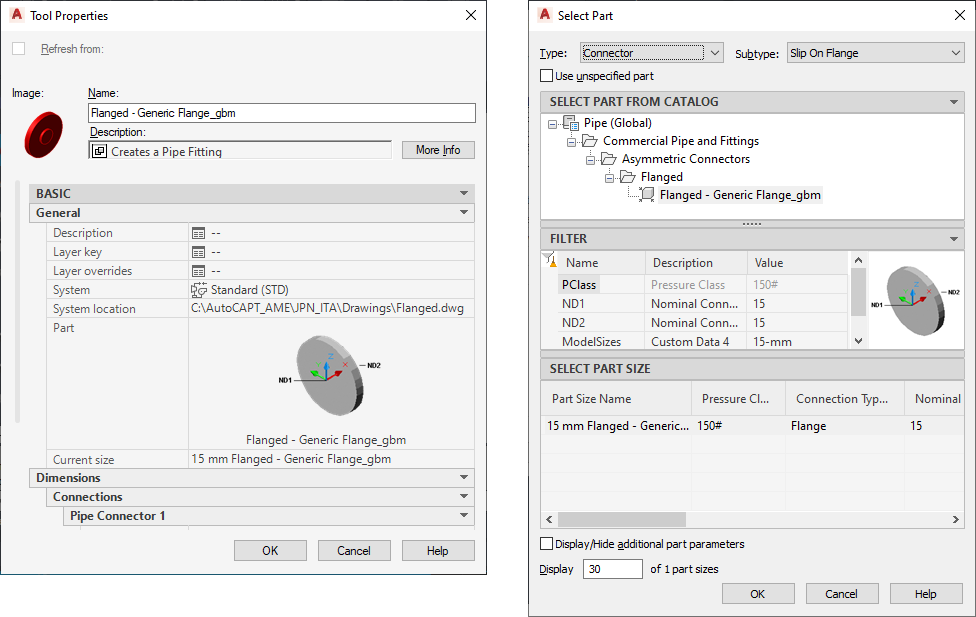
For all tools, you can define the properties of a tool in a tool palette, such as name and description. For many tools, you can also define additional properties, such as the layer key and layer key overrides of objects inserted with the tool, and the object style.
To change the properties of a tool
To select a part for property-based tools
To specify other properties
- Open the tool palette that contains the tool you want to modify.
- Right-click the tool, and click Properties.
- In the Tool Properties dialog box, enter a name for the tool.
- Click
 and enter a tool description in the Description worksheet (optional). Note: The software uses the tool description as the tooltip and also as the description when the tool is copied to a tool catalog in the Content Builder.
 - For property-based tools created from within the drawing, click the part image on the Tool Properties to open the Select a Part dialog box.

- In the Select a Part dialog box, choose a part from the catalog and optionally make other part and filtering selections. Tip: Select the Use unspecified part type to disable the part selections in this dialog box. This selection creates a tool on the tool palette that does not include specified properties. You can use this new tool to start the object’s Fitting Add command as you lay out the pipe run.
- (Optional) On the Properties palette, specify other values for additional properties, as follows:
If you want to specify… then… a layer key click the Layer key worksheet, select the layer key in the Select Layer Key dialog box, and click OK. layer key overrides click the Layer overrides worksheet, specify the overrides in the Select Layer Overrides worksheet, and click OK. Note: If you do not specify a layer key or layer key overrides, the layer assignments specified in the layer key style in the drawing are used. - Specify other properties that appear depending on the type of tool, such as System, Current size, Elevation, Nominal diameter, and Insulation thickness.