- In the Piping workspace, click


 .
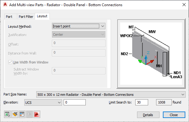
. - Navigate to Plumbing - Radiators in the tree view of the Add Multi-view Parts dialog box, and for Part Size Name, select a part size name from the list.
You can select a part size name for the radiator or let the software calculate the correct part size on the Layout tab (described later in this procedure).

- For Elevation, select a value.
- (Optional) Click the Display/Hide additional parameters check box to toggle between displaying or hiding additional parameters in this dialog box. Tip: You can click Details to view the available sizes for the current radiator.
- On the Layout tab, under Layout Method, select the method for adding the radiators to the drawing.
If you want to... Then... place radiators relative to every window in selected spaces select Spaces. place radiators relative to selected windows select Windows. specify 2 points for each radiator to be placed select Two points. place radiators by specifying the insertion point select Insert point. Command-line prompts will ask you to specify insertion points. 
- Specify the positioning options for the radiators.
If you want to... Then... center each radiator for Justification, select Center. place each radiator off center for Justification, select Left or Right, and for Offset, enter a distance. place each radiator a specified distance from a wall for Distance from wall, enter a value. - If you want the software to calculate the radiator size, select Use Width from Window. You can also specify a value for Subtract Window Width by to decrease the width by the distance specified.
The height and depth are predefined by the selected part size.
- Select the objects or points used to place the radiators.
If you selected this layout method... Then... Spaces select one or more spaces in the drawing or xref. The software places the radiators relative to each window in the selected spaces, according to the specified positioning options. The software adds the radiators to the drawing based on the location and dimensions of the specified windows. For each radiator, the software uses the closest available part size. This value is less than the window width minus the value for Subtract Window Width by.
Windows select one or more windows in the drawing or xref, and click a point inside the building. The software places a radiator relative to each selected window.
Two points specify the left and right points for each radiator to be added. The software applies the positioning options to the line defined by the specified left and right points. It calculates the radiator size using the distance between the 2 points instead of a window width.
Insert point specify insertion point - If desired, modify the settings in the Add Multi-view Parts dialog box and add additional radiators.