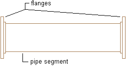
AutoCAD MEP 2024 toolset treats pipe joints as objects that are separate from the pipe segment. For example, a pipe segment with flanged connections actually comprises 3 objects: 1 pipe segment and 2 flanges.

The software adds joints as you draw pipe, based on selections made under Routing Options on the Pipe Properties palette. Having joints presented as separate objects renders more accurate systems that reflect the physical construction of the pipe system. You can create schedules for joint components, such as flanges or couplings. You can also manipulate the joints by changing their connection type or by refining their location on a pipe run.
The software categorizes pipe joints as fittings in the pipe parts catalog. Fittings are listed in the couplings directory and the asymmetric connectors directory. An example of an asymmetric connector is a socket weld flange. One side of the flange is configured with a socket to connect with a pipe, and the other side is a flange face that will connect with an adjacent flange.