Use this dialog box to specify datum identifier symbol details.
|
Symbol tab |
|||
|
Options |
|||
|
Datum on far side Changes the line type of surface indication leaders to indicate that the datum is on the far side of a component. The icon to the left of the check box changes to indicate the current state. Note:
This option is visible only in the revisions of drafting standards that permit surface indication lines. |
|||
|
Requirements Contains buttons and edit boxes to specify the datum. The edit boxes are named only in tooltips. Move the pointer over them to identify them. |
|||
|
Insert symbol Displays a palette enabling you to insert a special character at the current cursor position in the Datum Note or Thread Note boxes. The preview in the drawing area shows the special character while the dialog box shows the corresponding control key sequence. Note:
This option is visible only in the revisions of drafting standards that permit datum notes or thread notes. |
|||
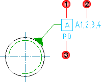 Datum identifier Specifies a label for the datum identifier (1 in the image above). You can specify a maximum of two characters for the label. |
|||
|
Datum note Specifies reference datum targets that correspond to one or more points on a surface. Typically this box contains a series of datum targets separated by commas (2 in the image above). Note:
This option is visible only in the revisions of drafting standards that permit datum notes. |
|||
|
Thread note Specifies which diameter of a screw or gear to use as the datum (3 in the image above). Note:
This option is visible only in the revisions of drafting standards that permit thread notes. |
|||
|
Leader and Text tab |
|||
|
Leader |
|||
|
Arrowhead Specifies the type of datum feature triangle to use at the end of the leader line. Select an arrowhead from the drop-down menu. The list of arrowheads conforms to the current drafting standard. The default arrowhead is the standard arrowhead for symbols. Set it in the Options dialog box. |
|||
|
Surface arrowhead Specifies the type of arrowhead to use at the end of the surface indication leader line. When the arrowhead is set to By Standard, it acquires the arrowhead from the current drafting standard. Thereafter, if you change the arrowhead selected for the current drafting standard (in the Datum and Feature Identifier Settings dialog box), the arrowhead for this symbol updates automatically. Note:
This option is available only if a surface indication line exists for the symbol you are editing. |
|||
| Edit object attachment | |||
|
Attach Attaches the symbol to a geometry in the drawing. |
|||
|
Detach Detaches the symbol. The symbol becomes a free-standing object. |
|||
|
Surface extension line Controls options for extension lines to the start point of the leader. Extension lines are drawn only if you move the start point of the leader beyond the end of the line or arc it is attached to. The options in this section are available only if extension lines for this symbol exist. |
|||
|
Offset from object Defines the distance between the surface extension line’s start point and the attached object’s end point. |
|||
|
Sync Loads values for the offset from the DIMEXO system variable. 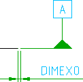 |
|||
|
Extension beyond leader Defines the distance between the surface extension line’s end point and the leader start point. |
|||
|
Sync Loads values for the extension from the DIMEXE system variable.  |
|||
|
Settings Opens the Datum and Feature Identifier Settings dialog box and enables you to edit the default settings for the current drafting standard. |
|||