Feature identifier symbols identify individual tolerancing zones that have the same value as a feature control frame shown elsewhere in the drawing.
 |
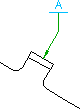 |
When you attach the symbol leader to an object, AutoCAD Mechanical toolset forces the first segment to be perpendicular to the attached object. The subsequent leader segments are forced to be horizontal or vertical. If you want to override this behavior, press the Toggle Symbol Leader Orthogonal Mode key (SHIFT + F, by default) as you move the crosshairs.

If you move the start point of the leader beyond the end of a line or arc, AutoCAD Mechanical toolset automatically draws extension lines. The default values for overshoot length and offset from end of leader is determined by the DIMEXE and DIMEXO system variables, respectively. AutoCAD Mechanical toolset does not create extension lines for splines.
Supported Drafting Standards
- BS 308 Part 3 (1990)
- CSN 01 3138 (1994)
- DIN EN22553 (1994)
- DIN ISO 1101 (1983)
- GB/T 1182 (1996)
- ISO 1101 (1983)
- JIS B 0021 (1984)
- GOST 2.308-79