It can be impractical to use a datum to control the tolerance of an entire surface, as the datum establishes a theoretically exact plane, line, or profile.
In order to specify practical data, relevant locations called datum targets can be selected and indicated on a drawing.
Symbol Description
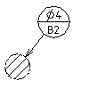
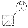
 Datum targets are circular frames divided in two parts by a horizontal line. The lower half is for a letter and a digit. The letter represents the datum feature, and the digit represents the datum target number. The upper half is for additional information, such as dimensions of the datum target area.
Types of the Symbol
You can attach datum targets to:
- a point indicated by a cross
- a line indicated by two crosses
- an area indicated by a hatched area
AutoCAD Mechanical toolset implements six types of datum target symbols depending on the termination types. They are:
None
Datum target without any termination.

Point
Datum target with a point termination.

Line
Datum target with a line termination.

Circle
Datum target with a circular termination.

Rectangle
Datum target with a rectangular termination.

Attached
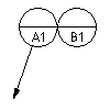
Datum target attached to another datum target.

Symbol Standard
You use the Datum Target Settings dialog box to set the appearance of the symbol. Available options conform to the current International Drafting Standard.
When saving into AutoCAD R12 format, the program does not save the hatch pattern in the circle or rectangle datum target. To work around this functionality, explode the symbol before saving as R12.
Supported Drafting Standards
- ASME Y14.5M (1994)
- BSI EN ISO 1101 (2013)
- BS 308 Part 3 (1990)
- CSN 01 3138 (1994)
- GB/T 1182 (1996)
- ISO 1101 (1983)
- ISO 7083 (1993)
- JIS B 0021 (1984)