In this exercise you learn how to work with a follower command that automatically follows a selected raster path.
Polylines can form a closed boundary or an open path. AutoCAD Raster Design toolset can automatically follow a selected raster path, stopping for your input when a decision point is reached. A decision point is typically an intersection, endpoint, or location with confusing geometry.
Related Exercises
Before doing this exercise, ensure that AutoCAD Raster Design toolset options are set as described in the exercise Exercise A1: Setting AutoCAD Raster Design Options and in the exercise Exercise V1: Setting Options and Creating Basic Vector Objects.
Exercise
- In the ..\Program Files\Autodesk\ApplicationPlugins\RasterDesign2024.Bundle\Contents\Tutorials\Tutorial6 folder, open the drawing file VTools_04.dwg.
- Ensure that the Raster Design Quick Bar is visible. If it is not, at the Command prompt, enter iqbar.
- On the
Raster Design Quick Bar, clear the
Stop at Raster Intersections button
 . It is cleared when it is not outlined.
Convert raster polylines
- To create a new polyline, on the ribbon, click
Raster Tools tab
 Vectorize & Recognize Text panel
  Followers drop-down menu
  Polyline Follower
 .
.
- Select a point on the edge of the cul-de-sac.
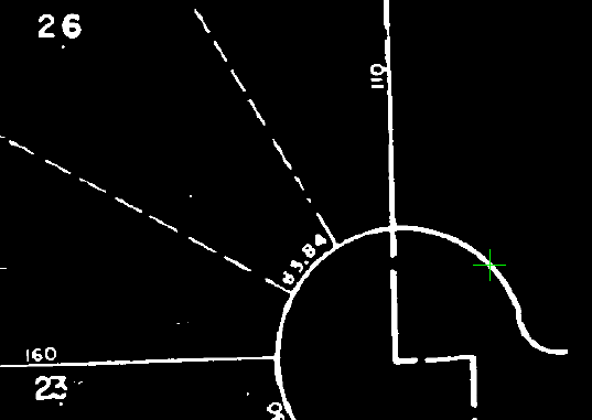
- Press
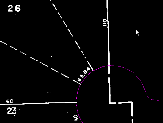
Enter twice, first to draw the polyline and then to remove the raster from behind the new vector.
Convert closed raster polylines
- On the
Raster Design Quick Bar, select
Stop at Raster Intersections.
This option enables you to direct the new vector entity when it reaches an intersection.
- To create a new polyline, on the ribbon, click
Raster Tools tab
 Vectorize & Recognize Text panel
  Followers drop-down menu
  Polyline Follower
 .
.
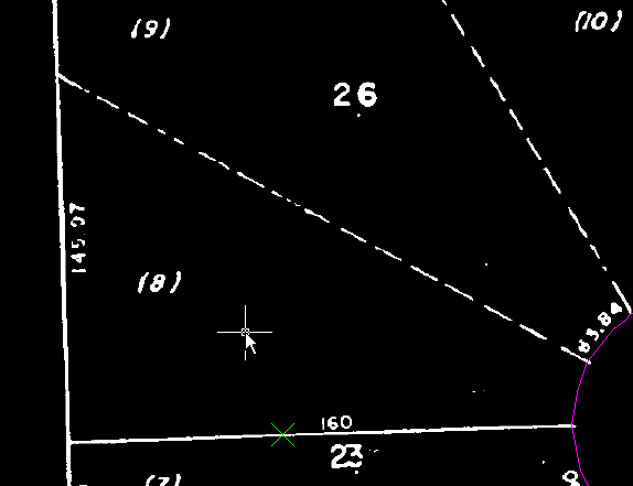
- Pick a point on the lot line between parcel (7) and (8).
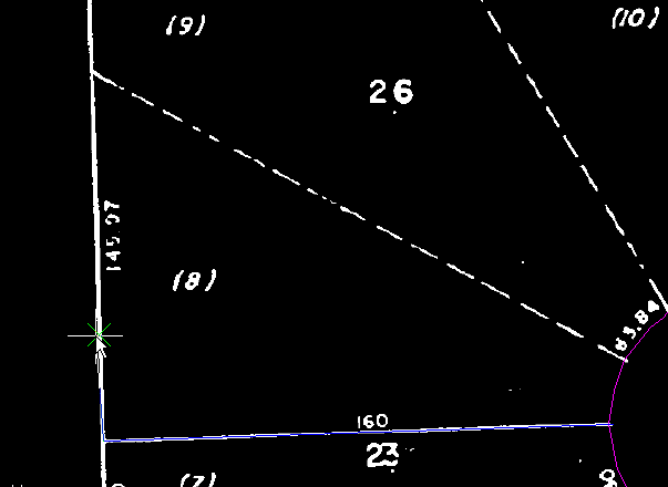
- When the follower reaches the end of the lot line, enter
d (Direction) then pick a point along the back lot line to specify the direction to trace the polyline around lot (8).
The Direction option is typically used at decision points.
- When the follower reaches the intersection between the back line and the dashed lot line, enter
d then pick a point near the beginning of the dashed lot line to continue to trace the polyline around lot (8).
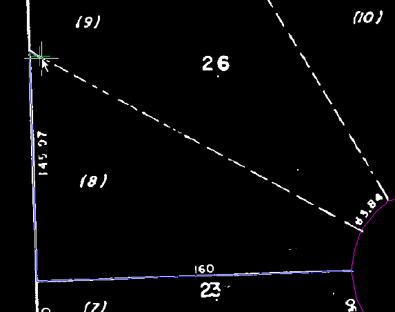
- When the follower reaches the cul-de-sac, enter
v (Vector), then pick the edge of the cul-de-sac to specify this as the vector line to follow.
The Vector option allows you to follow a vector polyline when lines or boundaries overlap.
- When prompted, select the beginning and end vertices of the curved polyline. The beginning is the upper vertex; the end is the lower vertex, where the polygon can be closed.
These points specify the direction and distance to follow on the vector polyline. The AutoCAD Endpoint OSNAP is activated for these point selections.
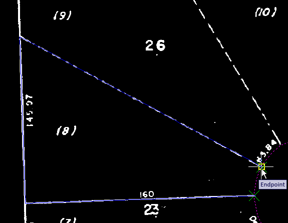
- Enter c to close the new polyline.
- Press
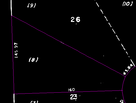
Enter to remove the raster from behind the new vector and exit the command.
The lot lines for Lot 8 were converted to a single polyline.
- Close the drawing without saving changes.