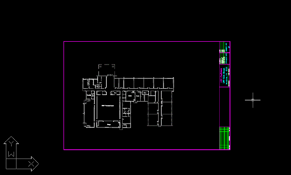
In this exercise you merge vector objects into a raster image.
By merging vector objects, you can make precise changes to your raster image using the power of AutoCAD drawing tools yet keeping your data in raster format.
In this exercise, you merge the following vector changes with the raster image of the floor plan:
- The new entrance
- The ramp that replaced the staircase
- The new classrooms
- The vector lines you drew to replace missing raster linework
When you merge vector objects into a raster image, you can control the following parameters:
- The line width of the raster linework created from the vector object(s), based on the color of each object
- Which vector objects to merge into the image
- Whether or not or not to create a new image for the merged data
- If display order should be respected when merging
- If an existing image should be expanded if necessary to accommodate the new data
Related Exercises
Before doing this exercise, ensure that AutoCAD Raster Design toolset options are set as described in the exercise Exercise A1: Setting AutoCAD Raster Design Toolset Options.
Exercise
- In the
..\Program Files\Autodesk\ApplicationPlugins\RasterDesign2024.Bundle\Contents\Tutorials\Tutorial4 folder, open the drawing file
Hybrid_06.dwg.
Select the color and width of the new raster linework
- To display the
Raster Pen Settings dialog box, on the ribbon, click
Raster Tools tab
 Edit panel (expanded)
  Raster Pen
 .
.
- Verify that the pen width for all colors is set to 3 pixels and click
OK.
Merge the vector objects into the image
- On the ribbon, click
Raster Tools tab
 Edit panel (expanded)
  Merge Vector
 .
.
- Draw a rectangle that includes all of the vector linework except the title block and border then press Enter.
- When prompted, enter
y to delete the vector objects you selected.
If you want to keep the vector linework, you can enter n when prompted. You can then freeze the layers that contain the vector linework so that the vectors are not displayed.
The following example shows how the drawing should appear after you merge the vector objects into the image.

Review the raster entities created from the vector objects
- On the ribbon, click
View tab
 Named Views panel
  View Manager
 . Then expand the
Model Views node and select the view named
TU_entry, click
Set Current, and click
OK. The linework for the proposed new entrance to the building is displayed.
- Set the current view to TU_classroom to see the linework for the proposed new classrooms.
- Set the current view to TU_ramp to see the linework for the proposed ramp.
- Set the current view to
TU_linework to see the area of the image where you replaced some of the missing raster linework with vector lines.
The raster lines created from the vector lines are smooth and distinct.
- Close the drawing without saving changes