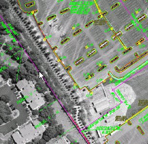
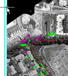
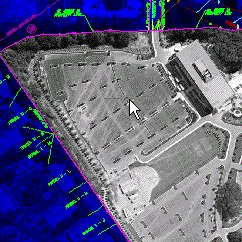
In this exercise, you use the Palette Manager to produce special effects on an image by applying an external palette.
You use the Raster Entity Manipulation (REM) feature to isolate the project extents from the original image. Then you create a new image from this REM region, apply a colored palette, and overlay the new image on top of the background. The effect you obtain can produce eye-catching graphics for presentations.
Related Exercises
Before doing this exercise, ensure that AutoCAD Raster Design toolset options are set as described in the exercise Exercise A1: Setting AutoCAD Raster Design Toolset Options.
Exercise
- In the
..\Program Files\Autodesk\ApplicationPlugins\RasterDesign2024.Bundle\Contents\Tutorials\Tutorial7 folder, open the drawing file
Palette_Manager02.dwg. An aerial photo inserts with the drawing.
Extract project area using raster entity manipulation
You use the REM function to isolate the area within the project boundary, then use the Palette Manager to tone the rest of the image which serves as the background.
- On the ribbon, click
Raster Tools tab
 REM panel
  Create Region drop-down menu
  From Existing Vector
 .
.
- At the command line you are prompted to select a closed vector object. Select the magenta boundary of the project.
Picking this boundary creates the REM object. The boundary color changes to red to signify that it is a REM object.

- Select the REM object, right-click and click
Convert to Raster Image.
The new image is given a default name of “Cingular Tutorial_1”, and it appears in Image Manager.
Tone the background image using Palette Manager
- On the ribbon, click
Raster Tools tab
 Edit panel
  Process Image drop-down menu
  Palette Manager
 . In the drawing, select the frame of the large, main image (not the one just created using REM).

In the Palette Manager dialog box, you see some image data, but other values are blank.
- Click the Convert to Color button. This action creates a complete grayscale palette as a basis for changes.
- Click
Palette menu
 Import. The
Import Palette dialog box is displayed.
The Import Palette dialog box may point by default to the support directory that contains several predefined palette files (.pf), including Blue.pf. If you need to navigate to this file, it is in the AutoCAD Raster Design toolset root directory ..\Program Files\Autodesk\ApplicationPlugins\RasterDesign2024.Bundle\Contents\Support.
- Select the
Blue.pf file. At the bottom of the dialog box, click the
Substitute option for importing palette files. The option replaces the gray levels in the original image, index by index, with the corresponding blue levels.
Import the palette
- In the
Import Palette dialog box, click
Open to apply the palette. The
Palette Manager dialog box is displayed and the results of the palette substitution are automatically applied to the image. Click
OK to close the
Palette Manager dialog box.
The project area is highlighted in gray tones, while the surrounding spatial data is muted by the blue tones.
Change the display order
Since the project image is obscuring some of the vector data, it needs to be moved back in the display. The easiest way to do this is to move both images to the back so they retain their relative positions with the project image over the background image.
- Select both images by pressing
Shift+Left-click inside the gray project image. Both images are highlighted in the
Image Select dialog box. Click
OK.

- Right-click and click
Image
 Send to Back. The vector data now shows over both images.
- After inspecting the results, close the drawing without saving changes or saving any images.