Markup Import and Markup Assist can make markups visible in the context of the drawing and assist you in making the appropriate changes.
Prior to this feature, you might look at another document (paper/pdf), find a requested change (markup), look back at AutoCAD and navigate to the appropriate place, and finally make the appropriate change with accurate drafting and CAD Standards.
 Download:
Sample files to use with the exercises in the following sections.
Download:
Sample files to use with the exercises in the following sections.
Markup Import
First, we'll import a markup file.
- Open the 2A-1-1.dwg.
- If the drawing is not on the South Partition layout, switch to it.
Note: You can work with Markup Import and Markup Assist in model space or in a layout.
- Click
.
Find
Note: Markup Import and Markup Assist are also available in AutoCAD for Mac and the AutoCAD web app.
- Browse to and select the markup file, 2A-1-1.jpg, to import.
Note: Markups can be imported from a PDF, PNG, or JPG. They can be of the entire drawing or a portion of the drawing.
If this is the first time you've used Markup Import, you'll see the following dialog box. Click I Understand.

The placement menu displays at your cursor's location. AutoCAD does its best to place the markup correctly, but it may not line up exactly. If you import an image you took with your phone or a hand drawn markup it may be a different scale, angle, or skewed a little bit. You have a number of options to correct the alignment if needed.
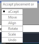
- Select Align from the menu. To align, you select two pairs of source and destination points. Source points are on the markup and destination points are on the drawing.
Note: You can't snap to geometry on the markup, but you can snap to geometry in the drawing.
- When prompted for the first source point, click on the upper right corner of the markup's title block (1).
- When prompted for the first destination point, click on the upper right corner of the drawing's title block (2).
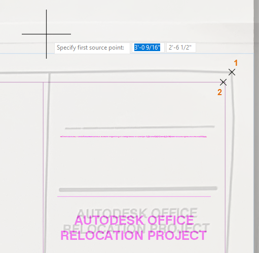
Next you are prompted for the second pair of source and destination points.
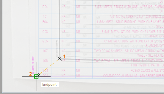
- Pan to the lower left area of the drawing.
- Select the points as indicated in the following image.
Since the two pairs of points define different distances and angles you are prompted to scale the markup, to better align with the drawing geometry.
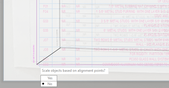
- Enter or select Yes.
The markup is scaled and aligned. It's still not exact, but it's closer.
If you aren't happy with the results, you can click Undo and either try again or use one of the other placement menu options.
- Click Accept.
Once you've clicked import and selected a file, a trace containing the markup is created. A Trace is like an overlay for your drawing where you can add feedback without altering the existing drawing.
Markup Environment
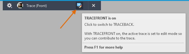
Before jumping into Markup Assist, let's get acquainted with the environment. A new trace is created containing the markup, and you are placed in the Trace environment. There are two modes:
- Trace Front. The active trace is in edit mode so you can contribute to the trace.
- Trace Back. The active trace is in view mode so you can edit the parent drawing while the trace is still visible.
Note: Markup Assist is only available in Trace Back mode.

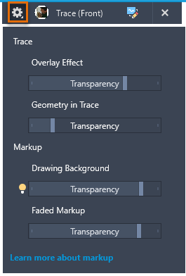
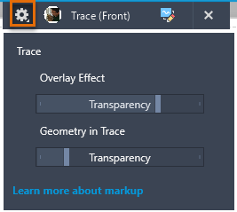
There are some differences in the settings depending on whether the trace contains an imported markup.
- Settings for a trace created by importing a markup. Experiment with the sliders.
- Settings for a trace created from scratch. Notice the Markup sliders are not available.
Markup Assist
With Markup Assist, you can act on the markups you import. Markup Assist can identify text, strikethrough text, leaders, revision clouds, instructional text, and PDF comments. When you act on a markup, such as inserting a revision cloud or Mtext, the object is added to the drawing, not the trace.
- Switch to Trace Back.
Markup Assist is only available in Trace Back. This is so you can update or insert drawing geometry based on the imported markups.
- Click to enable Markup Assist.
 Note: It can take some time for the markup boundaries to display.
Markups are indicated by blue dashed boundaries.
- Hover over any markup boundary to see the tooltip, which indicates the type of markup.
Type Tooltip Boundary 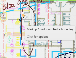
Text 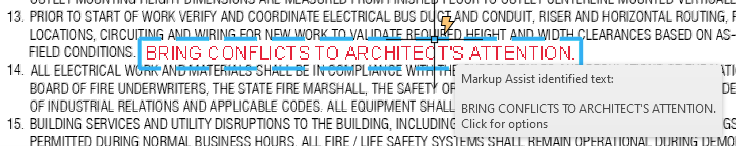
Strikethrough text 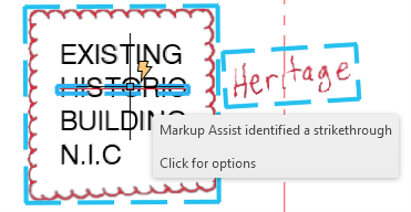
Instructional text 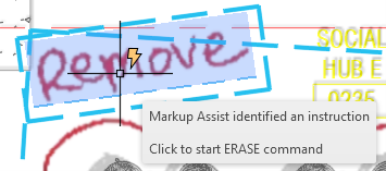
PDF comment 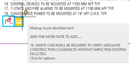
- Click on the markup boundary to act on the markup.
Let's try some examples in the following sections.
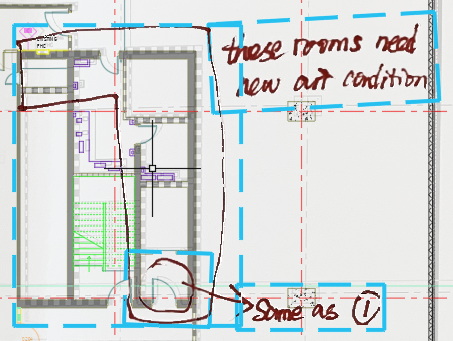
Revision Cloud Markup
- Click on the markup shown.
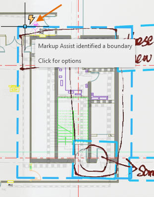
The Markup Assist dialog box displays.
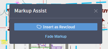
- Click Insert as Revcloud.
The revision cloud is inserted into the drawing on the current layer.
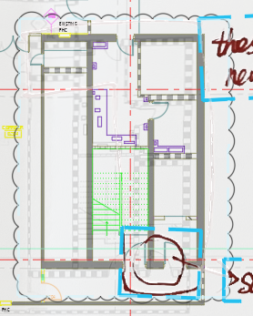
The markup's boundary is faded automatically. A markup can be acted on multiple times if necessary even once the boundary is faded.
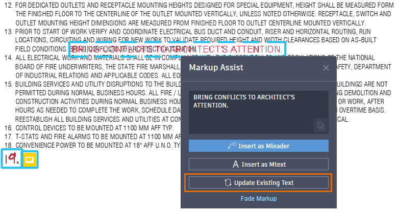
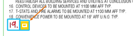
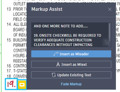
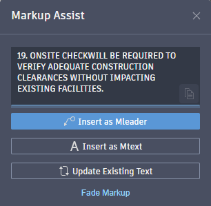
Text Markup - Insert as Mtext
- Click on the text markup boundary as indicated.
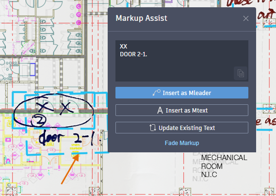
There are several options presented. In this example, we'll insert the text markup as Mtext. We'll try the Update Existing Text option later.
- Click inside the text box and edit the text as shown.
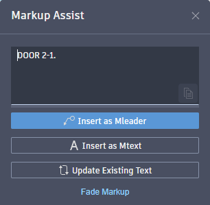
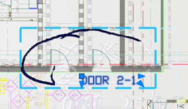
- Click Insert as Mtext.
- Select the location for the Mtext.
The Mtext is inserted using the current text style, and the markup is automatically faded.
Text Markup - Update Existing Text
- Open drawing 2A-2-0-2.dwg.
- Click . Find
- If the drawing is not on the North Power layout, switch to it.
- Browse to and select the markup file, 2A-2-0-2-MARKUPS.pdf, to import.
- Click Accept on the placement menu.
- Zoom to this area in the lower right.
In this example we'll look at the options for updating existing text.
- Double-click in the viewport to make sure you are in model space so the existing text can be selected.
- Click the markup boundary for the text and select Update Existing Text.
- Select the FIELD CONDITIONS text when prompted to select the text you want to replace.
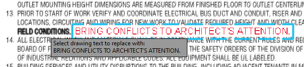 Note: If you can't select the text, press Esc to exit the current command. Double click inside the viewport and click the markup boundary again.
 - Select Append from the shortcut menu to add the markup text to the end of the selected text.
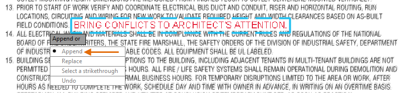
- Add a space in front of the added text, and click outside of the in-place editor or Close Text Editor on the Text Editor ribbon contextual tab, in the Close panel.

Text Markup - PDF Comments
If you imported a PDF file that contained added comments, those comments can be acted on like a text markup. A PDF comment markup appears as shown in this image.
- Click the PDF comment markup's boundary.
- Edit the text to remove what isn't needed as shown in the following image.
- Select Insert as Mtext and continue as described previously for text markups.
Note: If the text size and style doesn't match the existing text around it, use the MATCHPROP command to update the inserted Mtext. To learn more about MATCHPROP, see Have You Tried: Matching Properties.
Strikethrough Text
Markup Assist can recognize text markups that contain crossed-out text. Different options are provided for strikethrough text markups.
- Zoom into the area of the drawing shown in the following image.
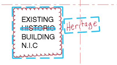
- Double-click in the viewport to make sure you are in model space so the existing text can be selected.
- Select the strikethrough markup boundary on top of the word HISTORIC.
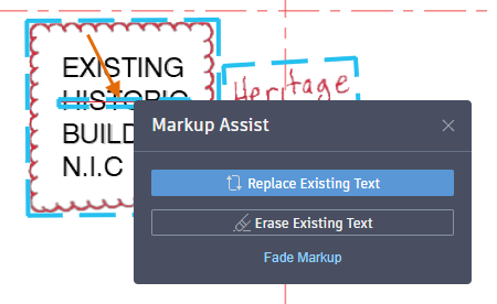
There are two options for strikethrough text; replace or erase the existing text. In this example, we'll replace the existing text with text from the markup next to it.
- Click Replace Existing Text.
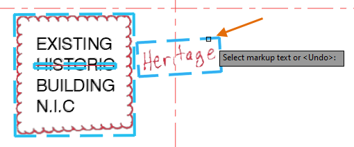
You are prompted to select the text you want to replace.
- Select the HISTORIC text itself, not the markup boundary.
You are prompted to select the markup text.
- Select the Heritage text markup's boundary.
The In-place Text Editor opens with the markup text available for you to edit, if necessary.
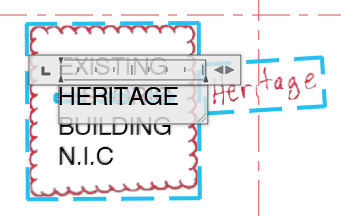
- Click outside of the in-place text editor or Close Text Editor on the Text Editor ribbon contextual tab, in the Close panel.
The Mtext is updated, and the markup is faded.
Instructional Text (English Only)
Sometimes a markup could be an instruction to do something, like move or erase. If Markup Assist identifies a text markup as instructional text, when you act on that markup, the associated AutoCAD command is started. Let's give it a try.
- Zoom into the area of drawing 2A-2-0-2.dwg as shown in the following image.
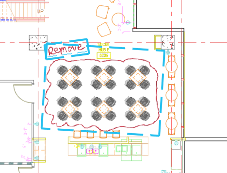
- Hover over the markup text, rather than the markup boundary, to see the associated command for an instructional text markup.
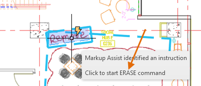 Note: Markup Assist recognizes natural language instructions in markups and associates them to corresponding AutoCAD commands used to carry out those instructions. For example, markup text that contains words like "Remove" or "Delete" can launch the AutoCAD ERASE command.
 - Click the markup text to start the ERASE command.
- Select the objects to erase that are indicated by the markup.
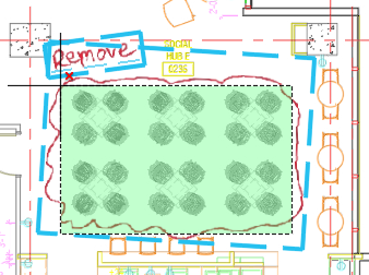
- Press Enter to complete the ERASE command.
Fade Markups
You already saw that a markup fades once you act on it. But what about markups that you don't need to act on? You can fade these so that they are less visible on the trace.
- Click FADEMARKUP on the Trace toolbar.
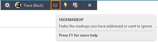
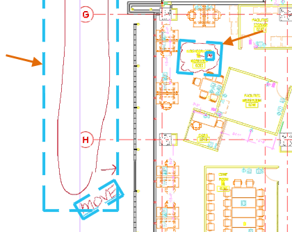
- Select the boundaries for each markup as shown in the following image.

Return to a Markup
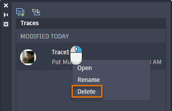
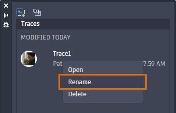
Once you exit a trace with an imported markup, you can return to it at any time. Before you return to the trace containing the imported markup, let's rename it so you can easily see what it contains.
- If the markup is still open, click Close on the Trace toolbar.

- Click . Find
- Right-click on the trace and click Rename.
- Enter
Markups from Eng.
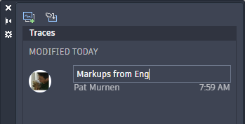
- Select the Markups from Eng trace to reopen the trace.
Summary
If reviewing and incorporating hand-drawn or PDF markups is a common part of your CAD workflow, you may want to try using Markup Import and Markup Assist to streamline the process. Hopefully, these features can save you time and improve accuracy when integrating markups into your drawing.