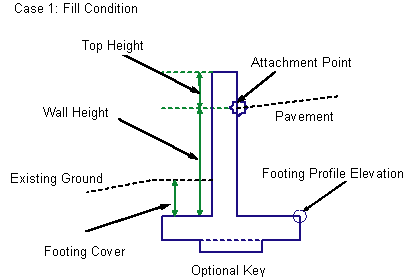
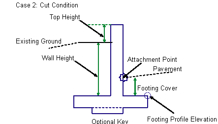
This subassembly inserts a retaining wall structure with both sides as vertical walls (no tapered side), and an optional key at the bottom.


Attachment
The attachment point varies depending on whether the retaining wall is in cut condition or fill. If it is in fill, the attachment point is near top of the retaining wall. If it is in cut, the attachment point is near the footing.
Input Parameters
Note: All dimensions are in meters or feet unless otherwise noted. All slopes are in run-over-rise form (for example, 4 : 1), unless indicated as a percent slope with a “%” sign.
| Parameter | Description | Type | Default |
|---|---|---|---|
| Side |
Specifes to insert the subassembly either on the right or the left side of the attachment point. |
Left / Right | Right |
| Wall Width | Specifies the width of the wall. | Numeric |
0.958 ft 0.292 m |
| Top Height | the distance between the top-of-the wall and the hook in fill or the new hook in cut. | Numeric |
1.320 ft 0.40 m |
| Footing Cover | The depth of cover from the top-of-footing to the finish grade line on the back side of the wall in fill or to the hook when in cut. | Numeric |
1.667 ft 0.50 m |
| Key | Species to add an optional key below the footing | Boolean | Yes |
Wall height is determined from top of the footing to attachment point of ground elevation on the vertical face, whichever is higher. Width of the footing, offset of wall vertical face, optional key dimensions, and the location of the key center, are all functions of the wall height.
Target Parameters
This section lists the parameters in this subassembly that can be mapped to one or more target objects, such as a surface, alignment, or profile object in a drawing. For more information, see To Specify Corridor Targets.
| Parameter | Description | Status |
|---|---|---|
| Wall Height | May be used to override the fixed wall height and tie to a profile. The following object types can be used as targets for specifying this elevation: profiles, 3D polylines, feature lines, or survey figures. | Optional |
| Target Surface | Existing ground surface name to determine retaining wall in cut or fill. The following object types can be used as targets for specifying this surfaces: surfaces. | Required |
Output Parameters
None.
Behavior
This subassembly can be inserted on either the left or the right sides. The attachment point is different for the fill or cut condition. In fill, the attachment point is assumed to be where the finish grade intersects the inside face of the wall, below the top of the wall, at a distance equal to the Top Height parameter. In cut, the attachment point is assumed to be where the finish grade intersects the inside face, above the top-of-footing at a distance equal to the Footing Cover parameter. The wall height is determined from the Wall Height or Profile input.
In fill, the sloping wall face is toward the center of the roadway. In cut, the sloping wall face is away from the roadway, towards the earth being retained. If the Key option is set to No, then the base of the footing is a single horizontal link. If the Key option is used, links to define the optional key are inserted.
Layout Mode Operation
In layout mode, the subassembly draws the retaining wall shape as specified by the input parameter values, assuming that the subassembly is in a fill condition.
Point, Link, and Shape Codes
The following table lists the point, link, and shape codes for this subassembly that have codes assigned to them. Point, link, or shape codes for this subassembly that do not have codes assigned are not included in this table.
| Point/Link | Codes | Description |
|---|---|---|
| P1 | RW_Front | |
| P2 | RW_Top | |
| P3 | RW_Back | |
| P14 | RW_Hinge | |
| P12 | RW_Inside | Could be used as breaklines in building datum surface |
| P5 | RW_Outside | Could be used as breaklines in building datum surface |
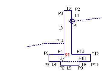
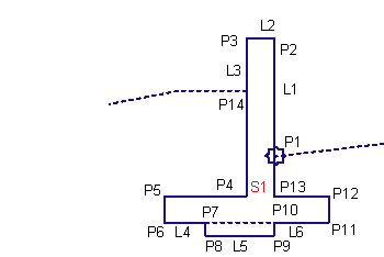
| L1, L2, L3 | Top | L1=P1 to P2; L2= P2 to P3; L3 = P3 to P14; |
| L4,L5,L6 | Footing_Bottom | L4 = P6 to P7; L5 = P8 to P9; L6 = 10 to 11; |
| S1 | RWall |
Coding Diagram
Fill Condition

Cut Condition
