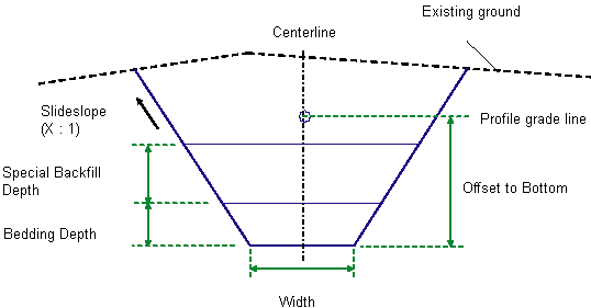
This subassembly creates a flat-bottom trench with equal sideslopes and up to three layers of backfill material.

Attachment
The attachment point is at the Offset To Bottom distance above the midpoint of the base of the trench.
Input Parameters
Note: All dimensions are in meters or feet unless otherwise noted. All slopes are in run-over-rise form (for example, 4 : 1) unless indicated as a percent slope with a “%” sign.
|
Parameter |
Description |
Type |
Default |
|---|---|---|---|
|
Width |
Width of the bottom of the trench |
Numeric, positive |
2.0 m 6.0 ft |
|
Sideslope |
X : 1 slope of the trench sideslopes |
Numeric, positive |
3 : 1 |
|
Bedding Depth |
Depth of the bedding layer |
Numeric, positive |
0.0 |
|
Special Backfill Depth |
Depth of the special backfill layer |
Numeric, positive |
0.0 |
|
Offset to Bottom |
The vertical offset down from the profile grade line elevation to the bottom of the trench. For example, if the profile runs along the top of a circular pipe, the vertical offset is the pipe diameter plus the distance from the bottom of the pipe to the bottom of the trench. |
Numeric |
0.0 |
Behavior
The elevation of the bottom of the trench is calculated as the profile grade line elevation minus the Offset To Bottom value. The horizontal trench bottom link is placed symmetrically about the attachment point offset at that elevation, and the sideslopes are extended upward to the Existing Surface. The horizontal Bedding link is placed at the given depth above the trench bottom. The horizontal Special Backfill link is placed at the given depth above the Bedding link.
Target Parameters
This section lists the parameters in this subassembly that can be mapped to one or more target objects, such as a surface, alignment, or profile object in a drawing. For more information, see To Specify Corridor Targets.
|
Parameter |
Description |
Status |
|---|---|---|
|
Existing Surface |
Surface model defining the existing roadway surface. The following object types can be used as targets for specifying this surfaces: surfaces. |
Required |
Output Parameters
None.
Layout Mode Operation
In layout mode, the trench and existing surface are drawn as shown below.

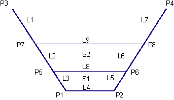
Point, Link, and Shape Codes
The following table lists the point, link, and shape codes for this subassembly that have codes assigned to them. Point, link, or shape codes for this subassembly that do not have codes assigned are not included in this table.
|
Point / Link |
Code |
Description |
|---|---|---|
|
P1, P2 |
Trench_Bottom |
|
|
P3, P4 |
Trench_Daylight |
|
|
P5, P6 |
Trench_Bedding |
|
|
P7, P8 |
Trench_Backfill |
|
|
L1 – L7 |
Trench Datum |
|
|
L1, L2, L6, L7, L8 |
Trench_Bottom |
|
|
L1, L7, L9 |
Trench_Daylight |
|
|
S1 |
Trench_Bedding |
|
|
S2 |
Trench_Backfill |
Coding Diagram
