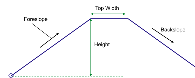
This subassembly inserts a noise barrier with the option to specify a topsoil material.

Attachment
The attachment point is at the inside edge of the barrier, which is typically at the outside edge-of-traveled way or shoulder or another road element.
Input Parameters
Note: All dimensions are in meters or feet unless otherwise noted. All slopes are in run-over-rise form (for example, 4 : 1), unless indicated as a percent slope with a “%” sign.
| Parameter | Description | Type | Default |
|---|---|---|---|
| Side |
Specifes to insert the subassembly either on the right or the left side of the attachment point. |
Left/Right | Right |
| Top Width | Width of the top barrier top. | Numeric, Positive |
1.0m 3.0 ft |
| Foreslope | Default slope of the barrier foreslope link. | Numeric | 1:1.5 |
| Backslope | Default slope of the barrier back slope link. | Numeric | 1:1.5 |
| Height | Specifies height of the barrier measure from the attachment point elevation. | Numeric, Positive |
3.00m 9.00ft |
| Topsoil Thickness | Specifies depth of material lining along daylight link. If a value of zero is entered, then no lining material is added. | Numeric, positive | 0.0 |
| Topsoil Shape Code | Specifies shape code for the topsoil material | String | Topsoil |
Target Parameters
This section lists the parameters in this subassembly that can be mapped to one or more target objects, such as a surface, alignment, or profile object in a drawing. For more information, see To Specify Corridor Targets.
| Parameter | Description | Status |
|---|---|---|
| Target Surface | Can be used to tie in the back of the barrier into an existing surface at the user defined slope. The following object types can be used as targets for specifying this surfaces: surfaces. | Optional |
Output Parameters
| Parameter | Description | Type |
|---|---|---|
| Barrier Top Elevation | Elevation of the mid point of the barrier top link | Numeric |
| Barrier Top Offset | Offset of the mid point of the barrier top link | Numeric |
| Topsoil Thickness | Thickness of topsoil material | Numeric |
| Backslope | Slope of the noise barrier backslope link | Numeric |
| Barrier End Offset | Offset of the end point of the noise barrier. | Numeric |
| Barrier End Elevation | Elevation of the end point of the noise barrier | Numeric |
Behavior
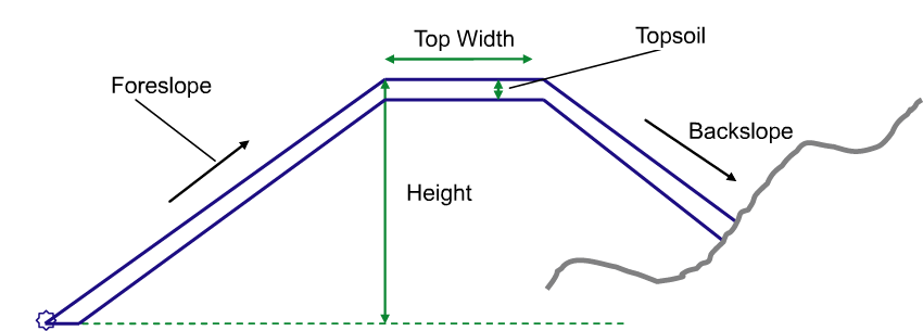
This noise barrier is introduced from the attachment point with the foreslope and backslope as specified by the user. If the Top width is set to zero value, then a triangular shaped noise barrier results. Further if a topsoil layer is selected for this subassembly – then a lined material layer is introduced as illustrated below. (Note: a horizontal link at the attachment point is introduced such that the thickness of the material is equal to the specified value).

If the backslope is tied into a surface, then that side height is adjusted to daylight into the surface as shown below.

If the backslope is not tied into any surface, then the height of that side is set with specified height. Further, if the surface at that point is higher than the top of the barrier then again backslope link is drawn downwards with specified slope and height parameters.
Layout Mode Operation
In layout mode, this subassembly draws the links showing the default parameters, including height for back slope.
Point, Link, and Shape Codes
The following table lists the point, link, and shape codes for this subassembly that have codes assigned to them. Point, link, or shape codes for this subassembly that do not have codes assigned are not included in this table.
| Type | Codes | Description |
|---|---|---|
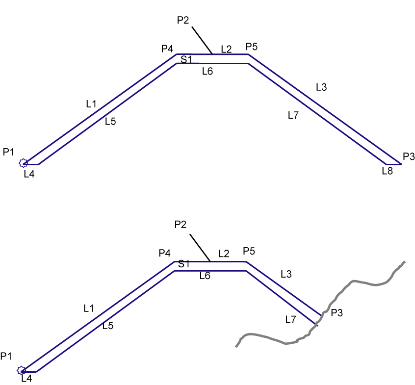
| P2 | RW_Top | Top point of the barrier |
| P3 | RW_Outside | Subbase daylight point |
| P3 | Daylight | Only if Target Surface is set |
| P4 | Bench_In | Inside edge of the barrier top (only if Top Width is non-zero value) |
| P5 | Bench_Out | Outside edge of the barrier top (only if Top Width is non-zero value) |
| L1, L2,L3 | Top | Finish grade of the shoulder |
| L1, L2,L3 | Datum | Only if the topsoil is thickness is set to zero |
| L4 to L7 | Datum | Only if the topsoil thickness is set to Positive value |
| L8 | Datum | Only if Target Surface is not set |
| S1 | User Defined Code | User defined code for topsoil (default - Topsoil) |
Coding Diagram
