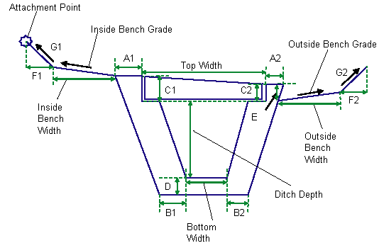
This subassembly creates a ditch structure to add to either the left or the right sides of the assembly.

Optionally, this subassembly can add daylight links on either side of the structure.
Attachment
The attachment point is at the innermost point on the grading links preceding the ditch structure. If the grading links on the inside are omitted, then the attachment point is on the innermost point of the inside wall.
Input Parameters
Note: All dimensions are in meters or feet unless otherwise noted. All slopes are in run-over-rise form (for example, 4 : 1), unless indicated as a percent slope with a “%” sign.
| Parameter | Description | Type | Default |
|---|---|---|---|
| Side |
Specifes to insert the subassembly either on the right or the left side of the attachment point. |
Left / Right | Right |
| Ditch Depth | Depth of the ditch on the inside | Numeric, Positive |
2.0ft 0.6m |
| Bottom Width | Bottom width of the ditch | Numeric, Positive |
1.0ft 0.3m |
| Top Width | Ditch opening at the lid | Numeric, Positive |
2.0ft 0.6m |
| Lid Gap | Gap between the lid sides and the inside walls | Numeric, Positive |
0ft 0m |
| A1 | Top inside wall thickness near the lid | Numeric, Positive |
0.45ft 0.15m |
| B1 | Inside wall thickness of the ditch structure | Numeric, Positive |
0.6ft 0.2m |
| C1 | Lid depth on the inside | Numeric, Positive |
0.6 ft 0.2 m |
| D | Ditch bottom bed depth | Numeric, Positive |
0.6 ft 0.2 m |
| Inside Bench Width | Width of the (optional) inside bench. Enter ZERO for no bench | Numeric, positive |
1.5 ft 0.5 m |
| Inside Bench Grade | Cross grade of the (optional) inside bench. It is measured away from the ditch structure edge, and a positive slope indicates rising bench from the ditch | Numeric, Grade type | 4% |
| F1 | Inside backslope link (optional) width. Enter ZERO value for no backslope link | Numeric |
1.0 ft 0.3 m |
| G1 | Slope of the (optional) inside backslope link. It is measured away from the ditch structure, and a positive slope indicates rising link from the start point | Numeric, Slope type | 1:1 |
| A2 | Top outside wall thickness near the lid | Numeric, Positive |
0.45 ft 0.15 m |
| B2 | Outside wall thickness of the ditch structure | Numeric, Positive |
0.6 ft 0.2 m |
| C2 | Lid depth on the outside | Numeric, Positive |
0.45 ft 0.15 m |
| E | Depth of the hinge point where the start of outside bench/backslope links is located | Numeric, Positive |
0 ft 0 m |
| Outside Bench Width | Width of the (optional) outside bench. Enter ZERO for no bench | Outside Bench Width |
3.5ft 1.1m |
| Outside Bench Grade | Cross grade of the (optional) outside bench. It is measured away from the ditch structure edge, and a positive slope indicates rising bench from the ditch | Outside Bench Grade | 4% |
| F2 | Outside backslope link (optional) width. Enter ZERO value for no backslope link | Numeric, Positive | 0.3 |
| G2 | Slope of the (optional) outside backslope link. It is measured away from the ditch structure, and a positive slope indicates rising link from the start point | Numeric, Slope type | 1 : 1 |
Target Parameters
This section lists the parameters in this subassembly that can be mapped to one or more target objects, such as a surface, alignment, or profile object in a drawing. For more information, see To Specify Corridor Targets.
Target Parameters: None.
Output Parameters
None.
Behavior
The subassembly builds the shape for a ditch structure, as shown in the above illustration. To omit the daylight and bench links, enter a zero value for the appropriate width parameters.
Layout Mode Operation
In layout mode, this subassembly draws as it is defined using the input parameters, starting from the attachment point.
Point, Link, and Shape Codes
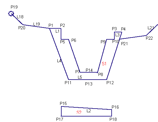
The following table lists the point, link, and shape codes for this subassembly that have codes assigned to them. Point, link, or shape codes for this subassembly that do not have codes assigned are not included in this table.
| Point/Link | Codes | Description |
|---|---|---|
| P1 | Ditch_In | |
| P1, P4 | Ditch_Back | |
| P2, P3 | Ditch_Lid_Face | |
| P15, P16 | Lid_Top | L2 is defined by these two points |
| P21 | Ditch_Back_Fill | |
| P23 | Ditch_Out | |
| L18, L19, L20, L21 | Top, Datum | |
| L1, L2, L3 | Top | |
| L4, L5, L6 | Datum | |
| S1 | Ditch | Ditch structure shape area |
| S2 | Lid | Lid structure area |
Coding Diagram
