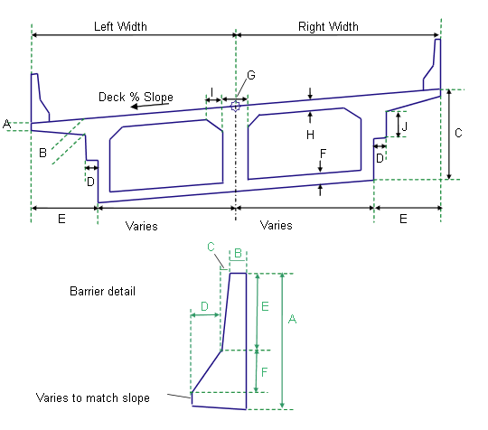
This subassembly creates a two-chamber box girder bridge shape with optional half-barriers.

Attachment
The attachment point is at the dividing line between the left and right lanes, on the bridge deck finish grade. The bridge section is built to the left and right sides.
Input Parameters
Note: All dimensions are in meters or feet unless otherwise noted. All slopes are in run-over-rise form (for example, 4 : 1) unless indicated as a percent slope with a “%” sign.
|
Parameter |
Description |
Type |
Default |
|---|---|---|---|
|
Left Lane Width |
Width of the left lanes of the bridge deck |
Numeric, positive |
5.34 m 17.8 ft |
|
Right Lane Width |
Width of the right lanes of the bridge deck |
Numeric, positive |
5.34 m 17.8 ft |
|
Deck Slope - Use Superelevation |
Specifies to use the superelevation slope for the bridge deck slope. |
List of options: No, Left Outside Lane Slope, Left Inside Lane Slope |
Left Outside Lane Slope |
|
Default Deck Slope |
Specifies default slope for the bridge deck |
Numeric, positive |
2.0% |
|
Include Barriers Omit Barriers |
Includes or omits barriers to each side of the bridge deck. |
Include / Omit |
Include |
|
Dimension A |
Deck thickness at the edge |
Numeric, positive |
0.200 m 0.667 ft |
|
Dimension B |
Deck thickness at the flange |
Numeric, positive |
0.300 m 1.0 ft |
|
Dimension C |
Total depth from finish grade to bottom of soffit |
Numeric, positive |
1.8 m 6.0 ft |
|
Dimension D |
Step width |
Numeric, positive |
0.150 m 0.5 ft |
|
Dimension E |
Total flange width |
Numeric, positive |
1.425 m 4.75 ft |
|
Dimension F |
Bottom girder thickness |
Numeric, positive |
0.170 m 0.5625 ft |
|
Dimension G |
Center girder thickness |
Numeric, positive |
0.250 m 0.833 ft |
|
Dimension H |
Top girder thickness |
Numeric, positive |
0.210 m 0.7 ft |
|
Dimension I |
Width of the top corner of the inside girder |
Numeric, positive |
0.300 m 1.0 ft |
|
Dimension J |
Step height |
Numeric, positive |
0.600 m 2.0 ft |
|
Barrier A (mm or inches) |
Height of the barrier at the center of median |
Numeric, positive |
810 mm 32 in |
|
Barrier B (mm or inches) |
As shown in diagram |
Numeric, positive |
131 mm 4.5 in |
|
Barrier C (mm or inches) |
As shown in diagram |
Numeric, positive |
59 mm 2 in |
|
Barrier D (mm or inches) |
As shown in diagram |
Numeric, positive |
125 mm 5 in |
|
Barrier E (mm or inches) |
As shown in diagram |
Numeric, positive |
557 mm 22 in |
|
Barrier F (mm or inches) |
As shown in diagram |
Numeric, positive |
178 mm 7 in |
Target Parameters
This section lists the parameters in this subassembly that can be mapped to one or more target objects. For more information, see To Specify Corridor Targets.
|
Parameter |
Description |
Status |
|---|---|---|
|
Left Width |
May be used to override the fixed Left Width and tie the left edge-of-deck to an offset. The following object types can be used as targets for specifying the width: alignments, polylines, feature lines, or survey figures. |
Optional |
|
Right Width |
May be used to override the fixed Right Width and tie the right edge-of-deck to an offset alignment at each station along the corridor. The following object types can be used as targets for specifying the width: alignments, polylines, feature lines, or survey figures. |
Optional |
Output Parameters
| Parameter | Description | Type |
|---|---|---|
|
Superelevation Axis of Rotation |
Indicates whether the subassembly supports the axis of rotation calculation. To view a description of the parameter, in the Properties window, hover the cursor over the parameter. For more information, see Profile Grade Line Adjustments During Superelevation. |
Static (Description) |
Behavior
The subassembly builds the links for the bridge deck and under-structure based on the input parameter values given. If the LI or LO options are used for the bridge deck, the superelevation slope for the left side is held constant across the entire width of the bridge.
If Include Barriers is True, one-sided New Jersey barrier sections are added at the left and right edges-of-deck. The slopes of the barrier bottoms adjust to match the deck slopes.
Layout Mode Operation
In layout mode, this subassembly draws the bridge structure and barriers as specified by the input parameter values.
Point, Link, and Shape Codes
The following table lists the point, link, and shape codes for this subassembly that have codes assigned to them. Point, link, or shape codes for this subassembly that do not have codes assigned are not included in this table.
|
Point, Link, or Shape |
Code |
Description |
|---|---|---|
|
P1, P3 |
EBD |
Edge of bridge deck |
|
P2 |
Crown_Deck |
Crown point on bridge deck |
|
L1 |
Deck, Top |
|
|
Bridge |
All exterior bridge substructure links |
|
|
Girder |
All interior bridge substructure links |
|
|
All barrier links |
Barrier |
|
|
S1 |
Bridge |
|
|
S2, S3 |
Barrier |
Coding Diagram
