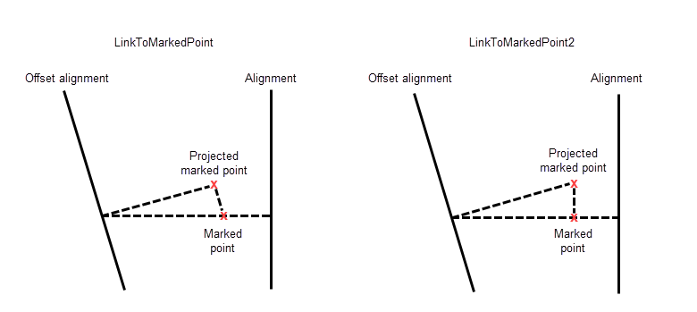
This subassembly is a general purpose utility to connect a link from the attachment point to a previously named marked point.
It can be used in a variety of situations, including connecting between adjacent roadways where the relative offsets and elevations vary, or across a gore area between converging roadways. Use the MarkPoint subassembly if the connecting point has not already been named.

In order for the LinkToMarkedPoint subassembly to work (draw) properly, it must be located below the MarkedPoint subassembly on the Construction tab of the Assembly properties. If the LinkToMarkedPoint subassembly is not located below the MarkedPoint subassembly on the Construction tab, you should select the Subassembly Group name in the Construction tab, then right-click and choose Move Up, so that the MarkedPoint subassembly is located above the LinkToMarkedPoint subassembly in the list.
The primary difference between the LinkToMarkedPoint2 subassembly and the LinkToMarkedPoint subassembly is in its application, when the marked point is on an offset assembly baseline comparing to the link. The following illustration shows the difference between the two subassemblies.

Attachment
The attachment point is at the beginning of the link. The link may go in any direction. The direction is determined by the location of the marked point relative to the attachment point. Be sure to name the marked point and set the marked point name in this subassembly.
Input Parameters
Note: All dimensions are in meters or feet unless otherwise noted. All slopes are in run-over-rise form (for example, 4 : 1) unless indicated as a percent slope with a “%” sign.
|
Parameter |
Description |
Type |
Default |
|---|---|---|---|
|
Marked Point Name |
Name of the marked point to connect to |
String |
None |
|
Link Codes |
A list of codes to be assigned to the link |
Comma-separated string |
Top, Datum |
|
Omit Link |
This parameter adds or removes the surface link. |
Yes\No |
No |
Target Parameters
This section lists the parameters in this subassembly that can be mapped to one or more target objects, such as a surface, alignment, or profile object in a drawing. For more information, see To Specify Corridor Targets.
Target Parameters: None.
Output Parameters
|
Parameter |
Description |
Type |
|---|---|---|
|
Begin Offset |
+/- offset of the beginning of the link |
Numeric |
|
Begin Elevation |
Elevation of the beginning of the link |
Numeric |
|
End Offset |
+/- offset of the end of the link |
Numeric |
|
End Elevation |
Elevation of the end of the link |
Numeric |
Behavior
A link is added from the attachment point to the given marked point.
Layout Mode Operation
In layout mode, this subassembly displays the link between the attachment point and the marked point.
Point, Link, and Shape Codes
None.
Coding Diagram
