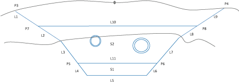
This subassembly creates a flat-bottom trench with equal sideslopes and allows for two surface types and will use the slope specified for the surface it is below. Up to three layers of backfill material are available. The width of the trench is determined by a user-specified width and minimum pipe cover.

Attachment
The attachment point is located along the target surface in the middle of the trench.
Input Parameters
Note: All dimensions are in meters or feet unless otherwise noted. All slopes are in run-over-rise form (for example, 4 : 1) unless indicated as a percent slope with a “%” sign.
| Parameter | Description | Type | Default |
|---|---|---|---|
| Sideslope | X : 1 slope of the trench sideslopes | Numeric, positive | 3 : 1 |
| Bedding Depth | Depth of the bedding layer | Numeric, positive | 0.0 |
| Special Backfill Minimum Cover | Minimum amount of special backfill cover placed over the highest pipe. The pipe is measured from the pipe’s top outer diameter. | Numeric, positive | 0.0 |
| Special Backfill Minimum Depth | Minimum depth for special backfill below the lowest pipe. The pipe is measured from the pipe’s bottom outer diameter. | Numeric, positive | 0.0 |
| Width | Width of the bottom of the trench | Numeric, positive |
2.0 m 6.0 ft |
| Pipe Network 1 Offset | Offset from the outer edge of the pipe to the trench sideslope | Numeric, positive | 0.0 |
| Pipe Network 2 Offset | Offset from the outer edge of the pipe to the trench sideslope | Numeric, positive | 0.0 |
| Sideslope Rock | X : 1 slope of the trench rock sideslopes | Numeric, positive | 1 : 1 |
Target Parameters
This section lists the parameters in this subassembly that can be mapped to one or more target objects, such as a surface, alignment, or profile object in a drawing. For more information, see To Specify Corridor Targets.
| Parameter | Description | Status |
|---|---|---|
| Existing Surface | Existing Ground surface to connect sideslopes to. The following object types can be used as targets for specifying this surface: surfaces. | Required |
| Rock Surface | Rock surface to connect sideslopes to. The following object types can be used as targets for specifying this surface: surfaces. | Optional |
| Pipe Network 1 | Used to specify Pipe Network 1. The following object types can be used as targets for specifying this pipe network: pipe networks. | Required |
| Pipe Network 2 | Used to specify Pipe Network 2. The following object types can be used as targets for specifying this pipe network: pipe networks. | Optional |
Output Parameters
None.
Behavior
In both cases the subassembly will determine the bottom of trench depth and trench width based on the location of a pipe or pipes in specified networks. The Special Backfill Minimum Cover is determined by from the top outer diameter of the highest pipe found at the sampled section. The Special Backfill Minimum Depth is determined by the lower outer diameter of the lowest pipe found at the sampled station. Whichever surface the sideslope is below, the appropriate slope is used (rock or regular).
Case 1: Single Pipe Network Selected

If only Pipe Network 1 is selected, the subassembly will search 3 feet (1 meter) from the controlling baseline to the left and right to find the pipe centerline at the sampled station. Apply the Pipe Network 1 offset value to both sides to determine the pipe width, or the minimum width, whichever is smaller. The offset value is applied from the outer wall of the pipe as shown in the illustration. The bottom of the trench is determined by the pipe bottom outer diameter, plus the Special Backfill Minimum Depth, plus the Bedding Depth.
Case2: Two Pipe Networks Selected

When two pipe networks are selected, Pipe Network 1 will be assumed to be on the left side of the baseline, Pipe Network 2 will be assumed to be on the right side of the alignment. The material depth of the Special Backfill Minimum Depth will be determined by the higher of the two pipe top outer diameters, plus the Special Backfill Minimum Cover value. The bottom of the trench depth will be determined by the lower of the two pipe bottom outer diameters, plus the Special Backfill Minimum Depth, plus the Bedding Depth.
Layout Mode Operation
In layout mode, this subassembly draws a trench as shown in the previous illustrations.
Point, Link, and Shape Codes
The following table lists the point, link, and shape codes for this subassembly that have codes assigned to them. Point, link, or shape codes for this subassembly that do not have codes assigned are not included in this table.
| Point/Link | Codes | Description |
|---|---|---|
| P1, P2 | Trench_Bottom | |
| P3, P4 | Trench_Daylight | |
| P5, P6 | Trench_Bedding | |
| P7, P8 | Trench_Backfill | |
| L1 - L9 | Trench Datum | |
| L5 | Trench_Bottom | |
| L1,L9 | Trench_Daylight | |
| L1, L9, L10 | Trench_Backfill | |
| L1, L2, L3, L7, L8, L9, L11 | Trench_Bedding | |
| S1 | Trench_Bedding | |
| S2 | Trench_Backfill | Trench backfill minus area of pipes |
Coding Diagram
