The ApplyAOR option in the Subassembly Composer has the following effects on points and links for rail subassemblies as they appear in the flowchart:
- Geometry before ApplyAOR is specified for an item in the flowchart is not adjusted when cant is applied.
- Geometry after ApplyAOR is specified for an item in the flowchart, and which is created so that it is directly or indirectly dependent on the item which has ApplyAOR specified, is adjusted when cant is applied.
Because of these effects, you can achieve the expected cant behavior by specifying the ApplyAOR option for one or more links and make subsequent points and links in the flowchart dependent on those links.
A validation process occurs in the Subassembly Composer to check whether the geometry that depends on items which have ApplyAOR specified will be updated correctly.
When cant preview values are defined on the Cant tab, and you select the ApplyAOR check box for a link which connects points start point (SP) and end point (EP) in the Subassembly Composer, if either of the two points (SP or EP) is referenced by other points or links before the operation of the new link, a red error marker is displayed on both the flowchart and the link. A detailed error message is displayed when you place your cursor over the error marker on the link.
Cant validation example
The following example illustrates the validation process and how to resolve errors.
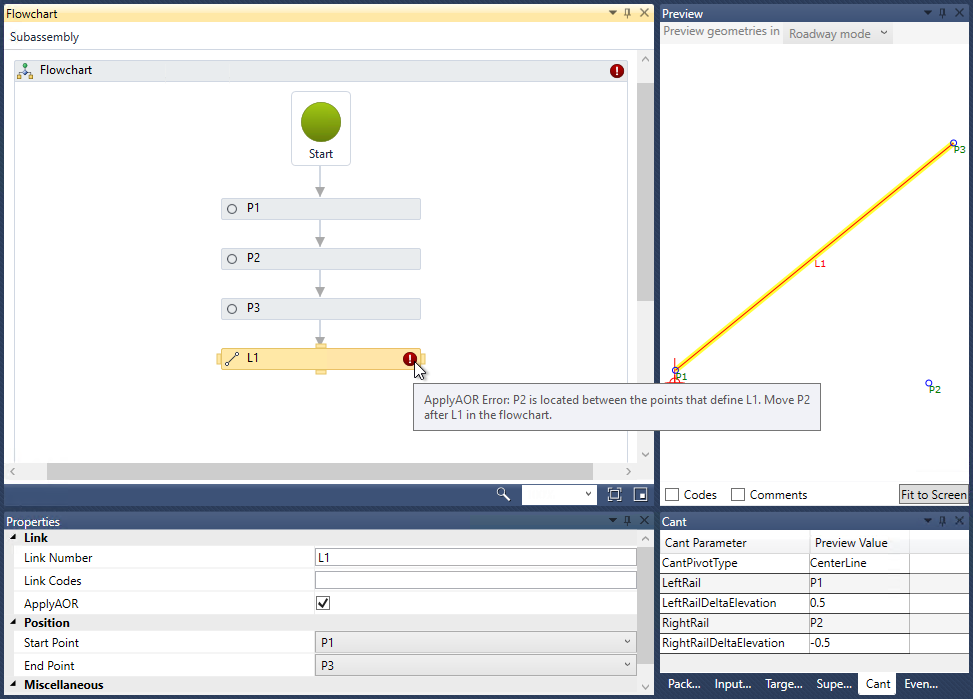
- P2 and P3 are both referenced from P1.
- L1 is defined from P1 to P3.
- Cant preview values, including those for LeftRail and RightRail, are defined on the Cant tab.
When ApplyAOR is selected for L1, an error marker is displayed on the link.

Because P2 is referenced from P1, and P2 is executed in advance of the ApplyAOR operation on L1, the location of P2 will not be adjusted correctly for cant, so the error marker is displayed.
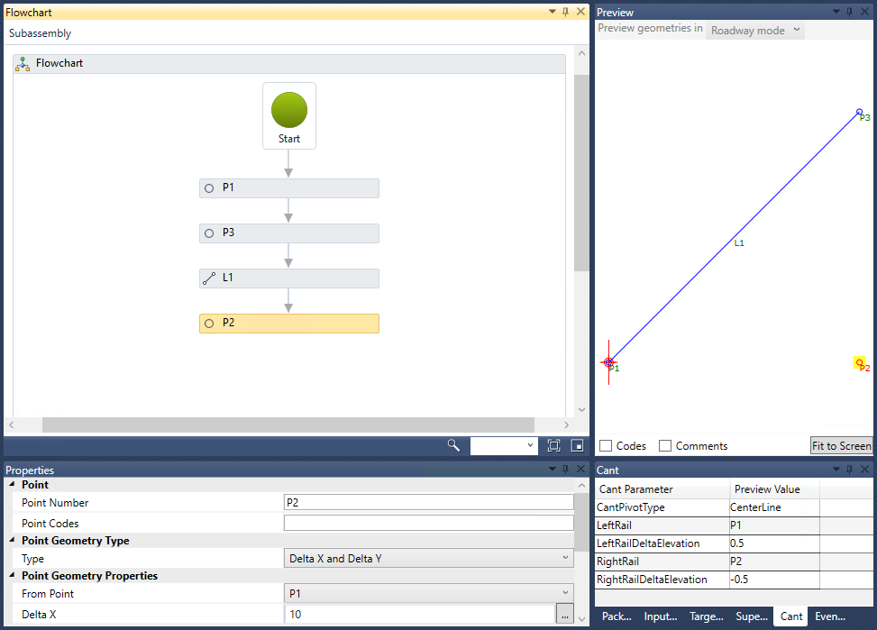
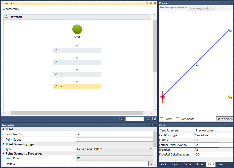
To resolve this, move P2 so that it is after L1, as shown in the following illustration.

The following illustration shows the addition of a new point named P4 which is created from P3. After L1 has been executed, the location of P4 will also be adjusted with P3.

Updating existing subassembly PKT files that use cant
If you open a previously-created subassembly PKT file in the Subassembly Composer in which the creation of a point or link contains an error similar to what is shown in the example above, the error markers will be displayed.
To resolve this, modify the sequence of the points and links as shown in the example above.