Use the Swap Pressure Network Parts command to change the type, family, and/or size of selected parts in a pressure network.
- Select a pressure network. The Pressure Networks Plan Layout contextual tab appears on the ribbon.
- On the Modify panel, click Swap Parts Find.
- Select the pressure network parts to swap.
- You can select the pressure network parts in either plan view or profile view.
- The selection set must be limited to parts in only one pressure network.
- If you select parts of more than one part type or part family, you are limited to changing the part size.
- Press Enter when you have completed your selection set.
- In the
Swap Pressure Network Parts dialog box, specify the Part Source.
The part source can be either the current pressure network parts list or a specific parts catalog. If you select a part from a parts catalog, the part is automatically added to the current parts list after the part swapping is completed if it has not already been added.
- Specify the Replacement Part.
Note: If you have selected multiple parts whose type and family are different, *VARIES* will appear in the list boxes and you are restricted to specifying the size for the replacement parts.
-
Specify the Elevation Reference. This setting controls how the elevation of the replacement part is determined.Important: If you do not select a replacement part, specifying an Elevation Reference and then clicking OK has no effect on the existing pressure network.
This setting defaults to Outside Top.
Note: Path-based pressure networks can only reference Outside Top when swapping parts.- If you specify a specific part
Elevation Reference (Outside Top, Crown, Centerline, Invert, Outside Bottom), the elevation of the point on the existing part will be used as the elevation of the same point on the new part.
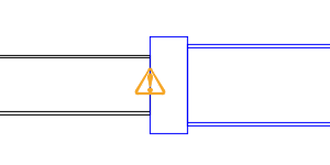
For example, if you select Centerline, the elevation of the centerline of the original parts is held as the elevation of the centerline of the replacement parts. In the following illustration which shows the effect in profile view, the blue fitting and pipe have been increased in size and Centerline was selected as the Elevation Reference.
- If you specify a surface and depth of cover, the elevation of the replacement part will be placed according to that surface elevation and cover depth.
For more information, see the Swap Pressure Network Parts dialog box topic.
- If you specify a specific part
Elevation Reference (Outside Top, Crown, Centerline, Invert, Outside Bottom), the elevation of the point on the existing part will be used as the elevation of the same point on the new part.
- Click OK.
After the parts are replaced, the Design Check command is run automatically to alert you to any issues that may be introduced by the changes. Warning symbols are placed in the drawing at the locations of the violations. You can hover your cursor over a warning symbol to view a tooltip which describes the violation.