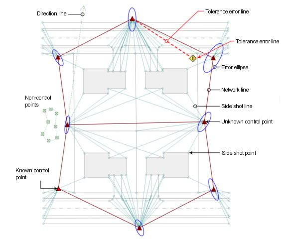
A survey network is a series of interconnected lines that represent the observed instrument setups, or stations. It contains all associated known control points, known directions, setups, and observations.
Tip: Use the Import Survey Data command to create a network and import data using the wizard interface. For more information, see Import Survey Data Wizard.
After you have imported or created data in the survey network you can insert the network into your Autodesk Civil 3D drawing as a network object.
The following illustration shows the network components:

Tips for working with Networks
- In a drawing you can hover your mouse over any network component to display a tooltip with component information.
- In the drawing, select a network component and right-click for options to browse to the survey data on the Survey tab, edit, or update the data.
- In SurveyToolspace, you can change the network display order using drag and drop functionality. When you drag and drop a network it is inserted after the network on to which it is dropped. Drag a network and drop it on the Networks collection to have it display first in the list.
- You can drag and drop a Network from the Survey tab in Toolspace into the drawing.
- Create a new network for each phase of a surveying project.
- Create a new survey network to use the Survey Command Window to perform calculations involving points from other existing survey networks. Data that you input is captured in the batch file, where you can make edits and run the file again with the corrections, if necessary, without affecting the integrity of the other survey networks.