Use this dialog box to generate a report that identifies the milling areas and offset details of a specified corridor.
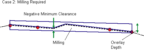
The corridor from which this report is generated must have been created using one of the milling subassemblies. Autodesk Civil 3D scans the corridor for stations at which milling occurs, the width of milling across the corridor, and the milling area, which is the area below the existing ground surface and above the subassembly overlay.

The milling report identifies the begin and end stations where milling occurs; left and right offsets from the centerline at the begin and end stations; and the area that is calculated from the previous data.
Select Report Components
- Select Corridor
-
Specifies the corridor on which to generate the report.
- Select Baseline
-
Specifies the corridor baseline on which to generate the report. The corridor assembly that is applied to this baseline must contain a milling subassembly.
Milling Tolerance
- Width
-
Specifies the difference in width that must exist between the left and right offsets from one station to the next in order for the milling area to be included in the current station range in the report.
The area between successive sample lines and the left and right offsets is used in the milling area calculation. If the difference in width between the offsets is less than the tolerance value, then the area is not included in the report.
- Thickness
-
Specifies the difference in thickness that must exist between successive sample lines in order for the milling area to be included in the report.
Report Settings
- Start Station & End Station
-
Displays the start and end stations for the specified baseline.
You can edit these values to change the range of stations included in the report. You can enter formatted or unformatted values, such as 2+50.95 or 250.95.
- Save Report To
-
Specifies the name and location of the resulting report. Click
 and specify the folder and file type.
 - Create Report
-
Generates the report and saves it to the specified location.
- Done
-
Closes the dialog box and discards changes to station ranges.