Create an observation from a traverse station using a horizontal angle measured on Face1 or Face2 of your instrument.
You can then input the measurements, using the Face1 (direct) and Face2 commands. These commands apply collimation (if set), and automatically average the sightings after you input observations.
Face1/Face2 angles can be collected in any order. If Face1 or Face2 observations are recorded, then a corresponding Face1 or Face2 backsight should also be recorded. In the case where Face1 or Face2 foresight observations are recorded without a Face1 or Face2 backsight, the setup's orientation is used in the foresight calculation.
Autodesk Civil 3D uses all reciprocal observations to a point (both foresight and backsight) by calculating an average horizontal and vertical distance of all the observations as long as the distance is a non-zero value to calculate the average horizontal and vertical position of a point. The correct average for all Face1/Face2 and reciprocal observations is applied when a network or traverse adjustment is performed. An adjustment may be done to get the correct average values whether there is a closed traverse or not.
To create an observation using a Face1 or Face2 angle, using the command language
- In Toolspace, on the Survey tab, right-click the network that you want to add points to, and click Survey Command Window.
- At the Command line, enter:
F1(point) [angle] [distance] (description)
or
F2 (point) [angle] [distance] (description
To create an observation using a Face1 or Face2 angle and vertical angle, using the command language
- In Toolspace, on the Survey tab, right-click the network that you want to add points to, and click Survey Command Window.
- At the Command line, enter:
F1 VA (point) [angle] [distance] [vertical angle] (description)
or
F2 VA (point) [angle] [distance] [vertical angle] (description)
To create an observation using a Face1 or Face2 angle and vertical distance, using the command language
- In Toolspace, on the Survey tab, right-click the network that you want to add points to, and click Survey Command Window.
- At the Command line, enter:
F1VD (point) [angle] [distance] [vertical distance] (description)
or
F2 VD (point) [angle] [distance] [vertical distance] (description)
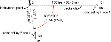
Example: Face1
NE 2 200 200
AZ 2 1 100
STN 2 1.585
BS 1
F1 VA 101 0 30.480 100 BS
! AZIMUTH: 101.6126 DISTANCE: 30.4800
! POINT 101 NORTH: 199.2280 EAST: 230.4702
! ELEV: <Null>
F1 VA 102 89.5370 15.304 101.2052 IP
! AZIMUTH: 191.1682 DISTANCE: 15.3013
! POINT 102 NORTH: 184.8457 EAST: 202.1159
! ELEV: <Null>
Points created Face1 command:
Point 101 is located by turning a horizontal angle of 0 right from Face1, and a vertical angle of 100 at a distance of 30.480 from the instrument point with the description BS.
Point 102 is located by turning a horizontal angle of 89.5370 right from Face1, and a vertical angle of 101.2052 at a distance of 15.304 from the instrument point with the description IP. Angles and distances are in the current units, unless you type a qualifying suffix.
Example: Face2
NE 2 200 200
AZ 2 1 100
STN 2 1.585
F2 1 200
F2 VA 101 311.4954 15.30 301.0355 IP
! AZIMUTH: 213.1080 DISTANCE: 15.300
! POINT 101 NORTH: 198.2901 EAST: 199.6429
! ELEV: <Null>
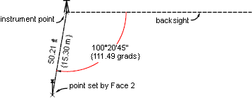
Points created Face2 command:
Point 101 is located a distance of 15.30 from the instrument setup at an observed angle right from the backsight of 311.4954. The actual physical angle turned is 111.49, with a vertical angle of 301.03. The description for the point is IP. Angles and distances are in the current units, unless you type a qualifying suffix.
Command Syntax
F1 (point) [angle] [distance] (description)
F2 (point) [angle] [distance] (description)
or
F1 VA (point) [angle] [distance] [vertical angle] (description]
F2 VA (point) [angle] [distance] [vertical angle] (description]
or
F1 VD (point) [angle] [distance] [vertical distance] (description)
F2 VD (point) [angle] [distance] [vertical distance] (description)
| Parameter | Definition |
|---|---|
| point | The point identifier of the new point. You do not need to assign a point number if auto point numbering is on. |
| angle | The measured horizontal angle. It is assumed to be clockwise (right). Use a negative number (-) to turn counter-clockwise (left). Type the horizontal angle in the current angular units (DMS, grads, decimal degrees, radians, or mils). |
| distance | The distance from the instrument point to the point being located. It is measured in the current units unless otherwise specified. The distance is assumed to be a horizontal distance unless VA is used. When VA is used, the distance is recognized as a slope distance. |
| vertical angle | The direction of the vertical angle (zenith, horizontal, or nadir). Type this value in the current angular units (DMS, grads, decimal degrees, mils, or radians). |
| vertical distance | The elevation difference from the instrument to the prism. If the prism is higher than the instrument, then this is a positive value. |
| description | An optional description associated with the point. If you use a description key, then specific information is assigned to the point. |