When creating a feature line you can manually enter an elevation, or you can assign elevations from a surface or from grading.
To assign feature line elevations from a surface
- Click
 Find.
Find.
- In the Create Feature Lines dialog box, select the Assign Elevations check box and click OK.
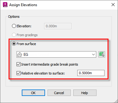
- In the
Assign Elevations dialog box, select the
From Surface option.
Note: If there are no surfaces in the drawing, the From Surface option is unavailable.
- Select a surface from the list or click the arrow icon to select it in the drawing.
- Select the Insert Intermediate Grade Break Points check box to insert intermediate grade breaks where the entity crosses surface TIN lines. Additional elevation points are created at these locations.
-
If you want the feature line to remain relative to the surface, select the
Relative Elevation to Surface check box and optionally enter a positive or negative offset value in the edit box. For more information, see
About Relative Feature Lines.
To manually assign feature line elevations
- Click
Find.
- In the Create Feature Lines dialog box, select the Assign Elevations check box and click OK.
- In the Assign Elevations dialog box, enter an elevation in the edit box select the Elevation option and click OK. If the object is a 3D polyline with varying elevations, the first point is set to the specified elevation and the rest of the points are raised/lowered by the same relative amount so that the elevation differences between the points remain.
To assign feature line elevations from a grading in the current site
- Click
Find.
- In the Create Feature Lines dialog box, select the Assign Elevations check box and click OK.
-
In the
Assign Elevations dialog box, select the
From Gradings option. This option is similar to the From Surfaces option but acquires the elevations directly from any gradings that it overlaps in the site that the feature line is to be created in.
Note: If there are no gradings in the drawing, the From Gradings option is unavailable.
- Select the Insert Intermediate Grade Break Points check box to insert intermediate grade breaks where the entity crosses surface TIN lines. Elevation points are created at these locations.