Insert a Model into a Factory Layout
Insert components from System Assets, User Assets, or external content libraries.
A factory layout can be populated with component data from multiple sources. You can insert components from the System Assets and User Assets content libraries, or you can insert external content. External content represents any data that has not been customized and placed in the Factory Assets library. This data includes standard Inventor part and assembly files, or files from other CAD products.
The Factory Assets library does not contain all the required components for a factory layout assembly. For example, most infrequently used components are not published into the library. For these situations, you can add a model directly to the layout.
Inserting a model at the layout origin
Complete the following steps to automatically place and ground the component at the layout origin (0, 0, 0). If the model has a defined insertion point, the insertion point aligns to the layout origin.
- Click Factory tab > Layout panel > Insert Model
 .
.
If you are working with Autodesk Vault, click Factory tab > Layout panel and then click the down arrow next to Insert Model to select Insert Model from Vault ![]() .
.
In the Insert Model dialog, browse to the folder location, select the file to insert into the layout, and select Open. The model appears and follows the cursor movement.
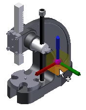
Press the right mouse button and select Insert Grounded at Origin.
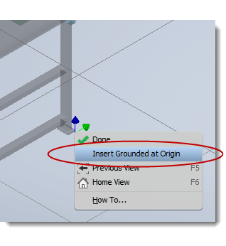
Right-click again and select Done to end the insert command.
Inserting a model in a specific location
Complete the following steps to select the insertion point:
Click Factory tab > Layout panel > Insert Model
 .
.If you are working with Autodesk Vault, click Factory tab > Layout panel and then click the down arrow next to Insert Model to select Insert Model from Vault
 .Note: This option is only available when the Vault client is installed.
In the Insert Model dialog, browse to the folder location, select the file to insert into the layout, and select Open.
Drag the selected component to the required location in the layout and press the left mouse button. The component appears inside a bounding box. The sides of the bounding box are parallel to the component origin planes. The insertion point is the corner of the bounding box that aligns with the origin coordinate system.
When locating the component in the factory layout assembly you can snap to the following:
- Grid Drag the component to the intersection of two grid lines on the factory floor and select once using the left mouse button. The Snap to Grid Snap Type must be enabled to allow grid snapping.
- Sketch Drag the component to a sketch entity on the layout and select once using the left mouse button. Components can be snapped to endpoints, midpoints, and along an entity. The Snap to Sketch Snap Type must be enabled to allow sketch snapping.
- Surface Drag the component to the surface of an existing asset and select once using the left mouse button. Examples for the use of this option include placing a crate on top of a pallet, or a vice on top of a workbench. The Snap to Surface Snap Type must be enabled to allow surface snapping.
- Vertex or Edge Drag the component to the vertex or edge of an existing asset and select once using the left mouse button. The Snap to Vertex or Edge Snap Type must be enabled to allow vertex or edge snapping.
- DWG Underlay Drag the component to a 2D entity on the drawing underlay and select once using the left mouse button. Components can be snapped to endpoints, midpoints, and along an entity. The Snap to DWG Underlay Snap Type must be enabled to allow underlay snapping.
- Point Cloud Drag the component to a single point in a point cloud and select once using the left mouse button. The Snap to Point Cloud Snap Type must be enabled to allow point cloud snapping.
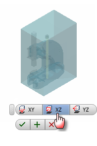
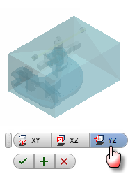
The component is placed in a default orientation in the XY plane. To adjust the orientation, select either the
 or
or  Mini-Toolbar options.
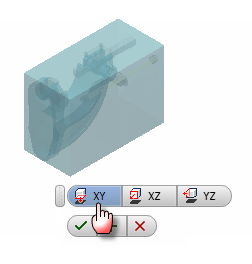
Click the OK button
 to place the component or click the Cancel button
  to cancel placement. Click the Apply button
  to place multiple copies of the model without exiting the command.
Use the Reposition tool to move or rotate the model, and then press Enter to exit the command or continue placing copies of the model.
Working with models from other CAD systems
You can import models in neutral formats, and in the native file format from many CAD systems. Inventor translates the model geometry data and creates an Inventor file.
Choosing whether to import a model as surfaces or solids
For most models, you can choose whether to import it as solids or surfaces. Choosing the best option depends on the type of model and how you plan to use it.
The Composite Surface option translates each face of the model independently and collects them into a single group of surfaces. This option is the default setting because it can ignore issues such as missing faces and gaps between edges. It can be easier to work with a composite surface if you do not have to make changes such as adding holes.
The Solid Model option also checks the edges of each face during translation. If the edges of adjacent faces touch either, the edges are stitched together. If all of the edges of a group of faces can be stitched together to enclose a volume, the result is a solid. If there are gaps or missing faces, the result is a collection of faces and quilts. If the original model was an assembly, there can be a combination of solids and surfaces. It is easier to work with a solid model if you have to modify the asset or change the appearance.
For assembly models, you can also choose whether to import the model as a multi-body solid or an assembly with individual components. If you import the model as an assembly, a part file is created for each part in the original assembly. File management is much simpler with a multi-body part, but you cannot move anything. For a factory asset such as a turntable, you need to import the model as an assembly show it in a different position.
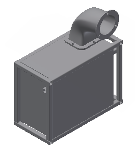
This model of a blower was imported as a multi-body solid. Since the exhaust elbow is a separate solid, you can delete it if you need a different part. You could also turn off the visibility of the covers to show the internal components.
Changing the appearance of models
Imported solid models use the standard Generic material and the Default color. In addition to the physical properties, each material also has a color and texture. If you change the material, the appearance also updates. You can also override the appearance of a material.
- A part can only have one material. To change the part material, select a Material from the list on the Quick Access Toolbar.
- To change the appearance of a solid part, select an Appearance from the list on the Quick Access Toolbar.
- If a part has multiple solid bodies, you can change the appearance of each solid separately. Select one or more solids in the window, and select an Appearance from the list on the Quick Access Toolbar.
There are two steps to change the appearance of a surface part:
- Right-click on the surface in the browser and clear the Translucent setting.
- Right-click on the surface in the browser again, and select Properties. Select an Appearance from the Feature Appearance list.
How do I insert a Revit file?
Revit files contain a 3D model of a building. In addition to architectural elements such as walls, doors, and columns, the model can include HVAC, plumbing, and other systems.
There are two settings that control how the Revit model is inserted. The 3D View defines the building orientation and which Revit model components are visible. The Import as options define how the Revit geometry is translated. The Single Composite Feature option combines all of the Revit geometry into a single surface feature. The Multi-body Part option creates a separate solid for each Revit component.
- Click the Insert Model icon and browse to folder, then select the file and click Open. Inventor loads the Revit file data, and then displays the Insert View dialog.
- Select a view from the 3D Views list to display the preview. Every Revit file has the default {3D} view, and some Revit files have multiple 3D views. A 3D view must be selected to insert the Revit file.
- Click the Import as drop-down arrow and select Single Composite Feature or Multi-body Part. The Single Composite Feature option inserts the file more quickly, but the Multi-body Part option makes it easier to change the appearance of the imported model.
- Click OK and place the model using the Snap options and the Reposition tool.