Scenarios can be used to model variations of a network simultaneously without the need to create separate branched networks.
For example, scenarios can be a very useful tool if used to investigate the impact of different parameters (pipe size, pipe material, for example) on simulations.
Working with Scenarios
As scenarios are derived from a base network, they do not appear in the Explorer Window as separate entities but are saved within the base network and are viewed by opening the base network and selecting the scenario to be viewed from the Scenarios Toolbar.
Any changes made to the base network are copied to scenarios.
If changes are subsequently made to the same field in the scenario so that the value of the field in the scenario is set to the same as the base, the link between the objects in the base and scenario is re-established and changes made in the base will be visible in the scenario again.
Network objects present in the base network but not in the current scenario are displayed as a faded grey colour in the scenario GeoPlan window. Display of these 'object ghosts' can be turned on/off from the Visual Page of the GeoPlan Properties Dialog.
The InfoWorks ICM Scenarios toolbar contains functionality allowing users to:
- View excluded objects in a grid.
- Restore en masse excluded objects to a scenario.
- Restore a selection of excluded objects to a scenario. The objects to be restored can be selected using the Excluded object select tool or the Excluded selected object selection option from the Selection menu.
Scenario Example
Example
A new housing estate is planned in the south-east of an existing town. A feasibility study is to be carried out to assess options for connecting the new estate to the existing sewer network.
The base network is the network in its current state. The background map shows the plans for the new estate, and currently there are no nodes or links serving it:
Scenarios can be used to model new estate connection options.
A scenario is created for each option to be assessed. An example is shown below:
Important Note about the Structure of Scenarios
Scenarios are not structured in the same way as most InfoWorks ICM objects therefore it is important to highlight the following points:
- Scenarios can be created from a base network. Any subsequent change to the base will cascade down to the scenarios.
- It is also possible to create copies of scenarios. This is equivalent to the Copy/Paste operation that computer users are accustomed to using, i.e.:
- Copied scenario are duplicates or direct copies of the scenario they originate from.
- Copied scenarios are independent from the original scenario.
- Scenarios that are copies of the same scenario are not linked in any way. Changes made to the original scenario do not cascade down to the scenario copies.
If we take the example below, where two scenarios, Scenario 1 and Scenario 2 have been generated from the base. Scenario 1 and Scenario 2 are independent from each other. However, changes made to the base will be cascaded down to both scenarios.
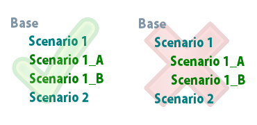
Scenario structure
Scenario 1_A and Scenario 1_B are duplicates of Scenario 1, and were obtained by copying Scenario 1. Scenario 1_A and Scenario 1_B are independent from each other. Making changes to Scenario 1_A will have no impact on Scenario 1_B and vice-versa. Similarly, editing or even deleting Scenario 1 will have no influence whatsoever on Scenario 1_A and Scenario 1_B. This is why the structure of scenarios can be represented by the image on the left (green tick) rather by than the one on the right (red cross).
Creating a Scenario
To create a new scenario
- Click the Create Scenario button (
 ) of the
Scenarios toolbar
) of the
Scenarios toolbar
- Select Scenarios
 Create scenario from the Network menu
- Open the
Manage Scenarios dialog by clicking the Manage Scenarios button (
 ) of the Scenarios toolbar or selecting the ScenariosManage scenarios option from the Network menu.
- This displays the Managing Scenarios dialog.
- Click on the Create button.
- The Create New Scenario Dialog is displayed.
- Enter a name for the scenario in the New Scenario Name box.
- A scenario ALWAYS originates from a base network (network in GeoPlan). However, should you want your newly created scenario to be the copy of another scenario rather than a copy of the base network, tick the Copy an existing scenario checkbox. This is particularly useful if you have scenarios on which you have made a large amount of changes and that you want to keep these changes to investigate further in subsequent scenarios. This saves you having to make all of these changes in a scenario copied from the base network.
- If the checkbox is ticked, select the scenario you want to make a copy of in the Scenario to copy drop-down box.
- The Notes box allows you to enter any desired notes about the new scenario.
- Click on OK to save your changes.
OR
OR
Renaming a Scenario
To rename a scenario
- Ensure that the scenario to be renamed is the
current scenario and click the Rename Scenario button (
 ) of the
Scenarios toolbar
) of the
Scenarios toolbar
- The Rename Scenario dialog is displayed
- Type in the new name for the scenario
- Click on OK to commit your changes
Deleting a Scenario
To delete a scenario
- Ensure that the scenario to be deleted is the
current scenario and click the Delete Scenario button (
 ) of the
Scenarios toolbar
) of the
Scenarios toolbar
- A message asking the user to confirm deletion is displayed. Click on Yes to confirm or on No to abort.
- Open the
Manage Scenarios dialog by clicking the Manage Scenarios button (
) of the Scenarios toolbar or selecting the ScenariosManage scenarios option from the Network menu.
- This displays the Managing Scenarios dialog.
- Select the scenario to be deleted and click on the Delete button.
- The scenario is deleted.
Note: You will not get prompted for confirmation when deleting a scenario via the Manage Scenarios dialog.
OR
Comparing a Scenario with the Base / Comparing Scenarios
To compare a scenario with the base network
- Open the
Manage Scenarios dialog by clicking the Manage Scenarios button (
) of the Scenarios toolbar or selecting the ScenariosManage scenarios option from the Network menu.
- Select the desired scenario
- Click the Diff button
- A report is displayed, highlighting the differences between the scenario and the base network it derives from.
- Close the Manage Scenarios dialog
- Close the report.
To compare two scenarios
- Open the
Manage Scenarios dialog by clicking the Manage Scenarios button (
) of the Scenarios toolbar or selecting the
Scenarios | Manage scenarios option from the
Network menu.
- Select two scenarios by using a combination of the mouse and the CTRL keyboard key.
- Click the Diff button
- A report is displayed, highlighting the differences between the scenario and the base network it derives from.
- Close the Manage Scenarios dialog
- Close the report.
Making a Scenario the base
It is possible to make a scenario the base. This is particularly useful if you have a scenario that you are happy with and that is the final result of your feasibility study.
- Open the
Manage Scenarios dialog by clicking the Manage Scenarios button (
) of the Scenarios toolbar or selecting the ScenariosManage scenarios option from the Network menu.
- Select the scenario you want to be the base network
- Click the Reintegrate button
- The scenario is promoted to base network and the "old" scenario disappears from the list of scenarios.
Creating a new base network from a scenario
It is possible to copy an existing scenario and make the new network the base. This is particularly useful if a particular scenario is favoured amongst other management options and that users wish to create a brand new network for this one scenario with a view of creating scenarios from it.
- Open the
Manage Scenarios dialog by clicking the Manage Scenarios button (
) of the Scenarios toolbar or selecting the ScenariosManage scenarios option from the Network menu.
- Select the scenario you want to copy.
- Click the Duplicate button
- The Common Tree Selection dialog is displayed. Type in a name for the new network and select a location within the model group.
- The new base network is checked out and appears in the Explorer window. The selected scenario and base network it is derived from are still present.
Editing Scenario notes
It is possible to add to or edit the notes for a scenario after the scenario has been created.
- Open the
Manage Scenarios dialog by clicking the Manage Scenarios button (
) of the Scenarios toolbar or selecting the ScenariosManage scenarios option from the Network menu.
- Select the scenario that you want to edit notes for
- Click the Edit Notes button
- The Edit Scenario Notes dialog is displayed. Carry out edits required and click Save
- If you also want to edit the notes for another scenario in the Manage Scenarios list, then use the Next or Previous buttons to step through the scenario notes until the required notes are display.
- When you have finished editing and have saved the notes, click Close to close the Edit Scenario Notes dialog.