Use AutoDrop to automatically size and place standard content. The following components can be placed with AutoDrop: Bolts (except Bolts  Other), nuts, washers (except ball washers), clevis pins, bearings, and circlips.
What's New:, 2023.2
- On the ribbon, click
Assemble tab
Component panel
Place from Content Center.

- In the Place from Content Center dialog box, locate the appropriate family.
- Select an AutoDrop-enabled family, and click OK. Alternatively, double-click an AutoDrop-enabled family.
- Use the AutoDrop commands to select component size and place the component.
- AutoDrop automatically finds the appropriate part, inserts it, and mates it in the context of the assembly. Geometry capable of supporting content within the selected family is highlighted, and AutoDrop previews recommended size and placement. As you move the cursor along the geometry, AutoDrop dynamically updates the preview until you make a selection. You use commands in the context menu to edit or accept the size and placement.
The status bar tip specifies which target geometry to select, and a tooltip displays information about the current family member.
- If there are more sizes available for the specified target, the preview shows a size grip.
Drag a grip to select a family member. The facet preview updates only when the facet information is already cached. Otherwise, only the grip position and the tooltip info are changed while dragging the grip. When the drag completes, the preview updates.
Double-click a grip to view a menu with available sizes for a quick selection.
-
If you click Apply
 or Done
 and several family members fit the existing criteria, AutoDrop displays a table to specify the member to insert. Select a member with desired material, thread type, bearing width, and so on.
- If you select target geometry that does not fully constrain the component position, the preview position is limited with the selection. For example, while dropping a bolt, you can select a circular edge, which fully constrains the bolt diameter and placement. You can also select a cylindrical face. Then, the bolt diameter is updated to fit the face diameter. The preview can be dragged only along the target axis. Planar faces normal to the cylinder are allowed for subsequent selection.
- If the selected family from Content Center does not contain part size fitting to the selected geometry, the part preview and the tooltip turn red.
To change the component size, right-click and select Change size from the context menu.
- AutoDrop automatically finds the appropriate part, inserts it, and mates it in the context of the assembly. Geometry capable of supporting content within the selected family is highlighted, and AutoDrop previews recommended size and placement. As you move the cursor along the geometry, AutoDrop dynamically updates the preview until you make a selection. You use commands in the context menu to edit or accept the size and placement.
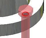
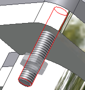
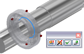
Place a bolt into an assembly
-
Pause the cursor on the countersunk face of the mating hole. Besides the part preview, a question mark and a context-sensitive icon are displayed on the cursor. The icon indicates the type of geometry required to place a part within the assembly.
-
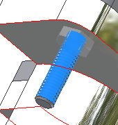
As you pause the cursor over legitimate geometry, the part preview automatically resizes to the closest match to the available part sizes in your content library. A tooltip displays the part name and the updated part size. If a part size corresponds with the target, the cursor changes to green check mark.
-
Click the target geometry. The AutoDrop toolbar is displayed. You can drag the grip to specify the bolt length. Only standard Content Center lengths are available.
-
If desired, you can lock the bolt position using the Lock Rotation icon.
-
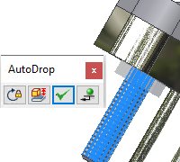
Click Apply to insert and mate the component.
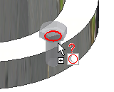
Place bolt into patterned hole
-
Pause the cursor on the hole edge. Besides the part preview, a question mark and a context-sensitive icon are displayed on the cursor.
-
As you pause the cursor over the target geometry, the part preview automatically resizes to use the closest match from the available part sizes. A tooltip displays the part name and the updated part size. If a part size corresponds with the target, the cursor changes to green check mark.
- Click the target hole edge.
 The AutoDrop toolbar is displayed with Follow Pattern selected by default. Switch off the button to insert a single component instead of a pattern.
-
You can drag the length grip to specify the bolt length, or double-click the grip to select a length from the list. Only standard Content Center lengths are available.
-
Click Apply to insert and mate the bolt.

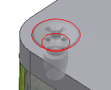
Place nut or washer into assembly
-
Select the bolt shank to identify the appropriate nut diameter and thread, or proper washer diameter. Then, select the target planar face.
You can select a circular edge of a hole to insert nut, washer, and so on. However, only the workflow that selects the bolt shank ensures that the thread information is used to identify the required fastener.
-
Click Apply.
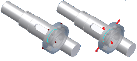
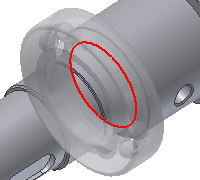
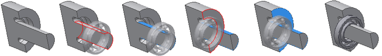
Place bearing into assembly
Insert the component from Content Center or from the Browser Bar Favorites. Once you drag the family to the modeling window, do the following:
- Pause the cursor on a housing edge or shaft edge. Besides the part preview, a question mark and a context-sensitive icon are displayed on the cursor. The icon changes depending on the last target geometry. For example, the cursor prompts for a shaft. When you pause on a hub, the cursor changes to a hub prompt.


-
Click the target geometry. The AutoDrop toolbar is displayed. You can drag the diameter grip to specify the bearing size, or double-click the grip to use the list of sizes. Only standard Content Center sizes are available. If the diameter grip is not displayed, there is only one bearing size fitting the target geometry.
 Note:
Note:Before you insert a component, right-click and select Change size to open a part family dialog box where you can edit the component.
 Use the Flip command to flip the bearing. This technique makes sense with tapered roller bearings, where you have two possibilities of how to mate them either on a shaft or housing.
-
Click Apply to insert and mate the component.
Place circlip into assembly
-
Pause the cursor on the target edge to select the appropriate part. Besides the part preview, a question mark and a context-sensitive icon is displayed on the cursor. The icon indicates the type of geometry required to place a part within the assembly, and differs for external and internal cicrclips.


-
As you pause the cursor over the target edge, the part preview automatically resizes to the closest match to the available parts in your content library. A tooltip displays the part name and the updated part size.
If a part size corresponds with the target geometry, the cursor displays a green check mark.


If the updated part size still does not correspond with the target, the cursor remains a question mark. (Example: the smallest circlip diameter is still too large to fit.) Both the part preview and the tooltip change color to red to highlight the discrepancy.
-
Click the target edge. The AutoDrop toolbar is displayed.

-
Click Apply to insert and mate the component.
Place multiple parts into assembly
If you select the target geometry and AutoDrop identifies a possibility to insert multiple occurrences of the same member. An Insert Multiple switch
![]() is available in the toolbar.
is available in the toolbar.
Set the switch off to insert a single part.
Set the switch on to populate all the highlighted targets.
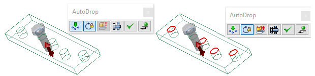
If the target geometry is patterned, you can insert a component pattern, multiple components, or a single component only, depending on the switch used.
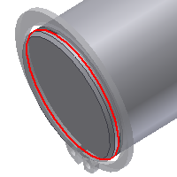
Place a part on a cylindrical face
When inserting a nut, selecting a cylindrical face allows you to select a nut that fits the bolt thread.
Place a bolt to a slot

-
Select the cylindrical face of the bottom hole to specify the bolt diameter. The preview is constrained along the cylinder axis.Note: The slot edges cannot be used for insertion.
-
Select the planar face to specify the exact placement.
Place a bearing
-
Select a cylindrical face to specify the bearing diameter.
-
Select planar face to finish the placement.
To constrain the part to the cylindrical face only

-
Select the cylindrical face.
-
Drag the part along the cylinder.
-
Use the context menu commands (Apply or Place) to finish the insertion.
The part is sized and constrained to the cylindrical face.