- Absolute maximum melt temperature
-
Displays the highest temperature the manufacturer recommends for the material melt process settings.
Processing at the Absolute maximum melt temperature can require special precautions and reduced residence times. Refer to the resin manufacturer processing specifications for more detailed advice on processing temperatures.
- Absolute ram speed profile
-
Used when key parameters of the injection molding machine are known, such as screw diameter and maximum injection rate.
Simulation results can be compared to actual results obtained from the injection molding machine.
- Air shot
-
An injection of polymer melts into the air, instead of into the mold. Acts as a "test run" to make sure that the machine is operating properly.
The cylinder is pulled back from contact with the sprue bushing and the injection piston is moved forward, forcing melted plastic from the nozzle. If you catch the melt in a metal cup as it exits from the nozzle, you can use a pyrometer probe to check the temperature. This method is one of the more accurate measurements of the melt temperature.
- Air trap
-
An air or gas bubble that is trapped by converging flow fronts, or trapped against the cavity wall, causes a surface blemish on the plastic part.
Prevent air traps by changing the gate location or the thickness of the part. Place vents at the location of the air trap
- Amorphous polymers
-
A family of polymers characterized by entangled polymer chains that are loosely bound.
Amorphous indicates that there is no preferred orientation of the molecules, relative to each other, without external force.
Amorphous polymers are in a super-cooled liquid state and generally shrink less than semi-crystalline polymers. These materials exhibit no x-ray diffraction pattern, because they are not crystalline in nature.

- Anisotropic shrinkage
-
Shrinkage that has different magnitudes in different directions.
Anisotropic shrinkage occurs in filled materials due to the restriction of shrinkage along the fiber length, which tends to be in the flow direction. This type of shrinkage also occurs in unfilled materials when the molecules have insufficient time to relax from the viscous elongation due to shear during flow.

- Annular gate
-
A type of gate that is used with hot runner system valve gates.
The reduced surface contact for an annular gate reduces the visibility of the injection point, which enhances the appearance of the part
- Annular runner
-
Runner with a heated central element or valve, or a heated outer surface with a central valve.
Annular runners can be used in the hot manifold, but most commonly are used in the hot drop, or in a valve gate.
- Aspect ratio
-
The relation between the width and height of a part area which affects the accuracy of an analysis.
The aspect ratios are especially important in sensitive areas such as gates, or gas channels in a gas-injection simulation.
When describing fibers, the term aspect ratio is the ratio of the length of the fiber to the diameter.

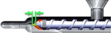
- Back pressure
-
Pressure that opposes the screw as it returns.
The purpose of increasing back pressure is to make it harder for the screw to return. This increases the shear heating and the mixing of the material, which results in improved polymer melt quality.
- Baffle
-
A cooling system component used to regulate and direct the passage of coolant fluid so that it can travel into difficult areas for more efficient cooling.
Inserting a metal plate into a cooling line forces the coolant to flow up one side of the plate and down the other. By interrupting the flow in the cooling line the baffle creates turbulence around bends and improves the heat transfer capability of the coolant.
- Balanced flow
-
The balanced filling of a mold with plastic melt so that the extremities of the mold fill at the same time and pressure.
Balanced flow leads to uniform orientation, uniform shrinkage, less internal stress and warpage, and cost savings through reduced material usage. Gate location, runner system design, and part thickness affect flow balance.

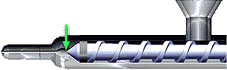
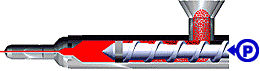
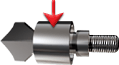
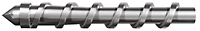
- Barrel
-
The cylindrical section of the plasticating chamber of an extruder or injection molding machine.
The barrel forms the chamber within which the plastic resin is converted from a solid form to a viscous melt.
- Barrel capacity
- The maximum weight of material that a machine can produce from one forward motion of the ram or screw.
- Barrel effect
-
The effect of material compressibility while the material is in the barrel of the injection molding machine.
This compressibility can be significant. A simulation that calculates and uses the barrel effect produces more accurate results.
- Base point
- The point that determines the position of the lifter assembly in the X or Y direction.
- Batch
-
The quantity of polymer that is made in one operation; also called a lot
- Bending moment
- The force or load applied to an entity, which produces bending of that entity around an axis.
- Birefringence
-
An optical property of transparent materials in which the refractive index of light passing through the material depends on the direction of polarization of the light.
Birefringence is a property of the material and the stresses experienced by the part. Birefringence can cause optical defects, such as uneven polarization and double images.
- Boss
-
A raised projection in a molded part.
A boss often has a hole in it to facilitate a mechanical fastener, such as a screw.
- Bounded runoff surface
-
A method used to create runoff surfaces.
Select the geometries and then set the directions for the start and end points of the geometries. If the face is selected as the geometry, the direction is not set.
- Bubble
-
A spherical, internal void caused by air or other gas trapped within a molded plastic product.
A bubble differs from a blister. The bubble is contained within the part. A blister is on or near the surface of the part and causes deformation of the surface. A bubble also differs from a void, which develops as a vacuum during cooling.
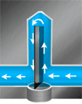
- Bubbler
-
A cooling system component comprised of a central circular channel that can be introduced into the mold to direct the passage of coolant fluid.
The bubbler enables coolant to travel into difficult areas for more efficient cooling. The coolant flows through the central channel and then out and around the outside of the channel to the outlet point.
Baffles and bubblers both increase flow turbulence due to the inclusion of additional bends in the coolant flow system. The increased turbulence enhances heat transfer. The geometrical shape of a bubbler enables the application of cooling to otherwise difficult to reach areas.
- Buckling
-
The conversion of in-plane membrane energy to bending energy, which usually involves large deformations of the part.
Buckling is the main cause of failure of a planar-thin structure under excessive in-plane loading.

- Burn mark
-
A defect that appears as a brown or black mark on the surface of a plastic part.
Sometimes an unvented air trap occurs when the trapped air is heated very quickly during compression and the surrounding plastic is burned. This condition can cause a burn mark.
Ram speed profiling, which gives air more time to escape from the mold, is often used to prevent this problem.

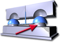
- Cavity
- The region or space within the mold into which plastic is injected to form a plastic part.
- Center gate
-
A gate which is located in the center of the part.
The center gate can be a sprue (direct) gate or pinpoint gate.
- Charge stroke
-
The distance between the screw back position and the zero screw position of an injection molding screw; also called the shot size
The charge stroke is a measure of the polymer available for injection for each plastic part.
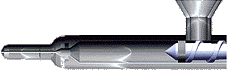
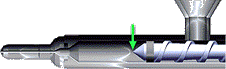
- Check ring
-
A sliding non-return valve found on the front of the screw.
The check ring allows molten plastic to flow forward to the front of the screw during plastication, and prevents flow back into the screw during injection. Because the check ring is a high wear item, it can leak during injection, reducing the pressure that is applied to the molten plastic.
- Chiller
-
A self-contained system that includes a refrigeration unit and a coolant circulation mechanism containing a reservoir and a pump.
Chillers maintain optimal heat balance by constantly recirculating chilled cooling fluids to injection molds.
- Circular runner
-
The most commonly used cross-section with the best volume-to-surface ratio.
Care must be used when cutting circular runners so there is no mismatch at the parting line.

- Circular sprue
-
A sprue with a non-tapered circular cross section.
Circular sprues are typically used as the entrance to hot manifold systems.
- Circular tapered arc gate
-
A gate that is used when presentation and disfiguration of the top face of a part is important. It is also called banana, winkle, cow-horn, hook, under-hung, jump, bent-tunnel and cashew gate
The circular tapered arc gate tunnels down from the parting plane and comes up on the underside of the part.
- Circular tapered gate
-
A common type of gate used with two-plate tools; also called subgate, submarine, or tunnel gate
The circular tapered gate is tapered from the runner to the part.

- Circular tapered runner
-
A runner with a circular cross section and a tapering diameter along the length of the runner.
Circular tapered runners are most often used in the runner drops for three-plate tools.
- Circular tapered sprue
-
A tapered circular sprue that is used in a cold runner tool
The circular tapered sprue is the entrance to the tool flow path.
- Clamp capacity
- A measure of the largest projected area of cavities and runners that an injection molding machine can safely hold closed at full molding pressure.
- Clamp force
- The force required to hold the mold closed while the plastic being injected into the cavity exerts an opposing pressure.
- Closed loop controller
-
A system that responds to feedback from transducers that measure the value being controlled. The system automatically adjusts to ensure plastic part production stays within predetermined tolerances.
For example, you can control cavity pressure. Place a transducer in the cavity and use that measurement to adjust the pressure on the plastic in the injection molding cylinder.
- Cold slug
-
An amount of cold polymer that can form in the nozzle between shots.
If it is not accounted for in the runner design, the cold slug can block the gate. To ensure that the cold slug does not block the gates, a cold slug well can be added to the runner system.
- Cold slug well
- A small extension of the runner system beyond a sprue or runner intersection, large enough to accommodate a cold slug of material.
- Compensating phase
- The period during the injection molding process when plastic is injected to compensate for the shrinkage of the plastic as it cools.
- Compressibility model
-
Describes the relationships between pressure, temperature, and the volume (PVT) of the plastic material.
Heated plastics are compressible and the compressibility of a material affects the volume of plastic required to produce a finished part. This software uses the 2-Domain Modified Tait PVT compressibility model with 13 coefficients.
- Control limits
-
Statistically determined values between which a control variable is allowed to range without adjusting the process.
Control limits provide an indication of the variation in the injection molding process.
- Cooling channel
-
A passageway in the mold, used to circulate water or another cooling medium around the mold. The cooling medium controls the temperature of the metal surfaces in contact with the plastic that is being molded.
Cooling channels are typically connected to form a circuit. Cooling channel configurations can be serial or parallel.

- Cooling time
-
The time required for the part to cool sufficiently to eject from the mold.
The net cooling time starts at the end of the holding phase. Gross cooling time starts at the end of the velocity phase and so includes the packing phase, holding phase, and the net cooling time.
- Core
-
The section of the mold that shapes the inside of a molded part.
- Core cavity plate clearance
-
The clearance between the fixed half and the moving half of the mold.
- Core pin
-
A steel rod that protrudes into the mold cavity to create a through hole or a blind hole in a part.
The core pin can be easily replaced with a core pin of a different diameter to create holes of different sizes to suit your design requirements.
- Core pocket depth
-
he distance between the XY work plane of the mold base assembly and the bottom face of the layout.
- Cracking
-
The formation of a narrow separation in a plastic component.
Cracking is caused when chemical bonds rupture due to internal and external stress.
- Crystalline morphology
-
The shape and size of the crystallites formed as a result of the specific mold design, part geometry, and processing conditions.
The shape and size of crystallites can significantly affect the molded material properties.
- Crystalline polymers
-
A family of polymers characterized by the ability of their molecules to form an ordered arrangement during solidification.
Because the molecules are able to fit closely together in an ordered state, crystalline polymers are typically more dense than amorphous polymers. No polymer can reach 100% crystallinity. Some molecules remain in a disordered state and form an amorphous part of the material.
Crystalline polymers display an X-ray diffraction pattern, which can be used to detect the degree of crystallinity (from the intensity) and identify the polymer (from the pattern).

- Crystallinity
-
The degree to which the number of molecules in a polymer reach an ordered state when solidified compared to the portion of molecules that remain in a disordered state.
Amorphous polymers have 0% crystallinity, but no crystalline polymer can reach 100 percent crystallinity.
- Crystallization
-
A level of crystallinity achieved is determined by cooling rates. The rate of crystallization is a function of both temperature and time.
Rapid cooling rates are associated with lower levels of crystalline content and the opposite is also true. Degrees of crystallinity affect the level of shrinkage. Higher crystallinity results in greater shrinkage.
Thick regions of injection molded parts tend to cool slowly relative to thinner sections, and so thick sections have higher crystalline content and greater shrinkage.
During cooling, some polymers form ordered molecular structures called crystalites.
- Cure
-
A stage reached by a thermosetting material that is sufficiently cross-linked to form a solid; cross linking is the result of a chemical reaction.
Sometimes the term cure is used to describe the solidification of thermoplastics; This physical process removes heat from the thermoplastic.
- Cushion
-
The distance between the forward screw position and the zero screw position.
The cushion contains polymer left in the barrel after the cavity is filled. Most of the melt in the cushion is then used for compensation flow during the packing stage.
- Cycle time
-
The time from the ejection of one part to the ejection of the next part.
Cycle time is the sum of:- Filling time
- Packing time
- Cooling time
- Mold open time
- Decompression
-
The movement of the screw away from the nozzle without rotation; used to prevent drooling.
Decompression can be used for low viscosity materials, such as PA-66, where the nozzle does not have a valve gate to prevent drooling.
- Delamination
-
A localized separation of the part surface.
The most common cause of delamination is excessive injection velocity.

- Density
-
Measured by dividing the mass of a plastic part by its volume.
A part is more dense when it has a larger mass (number of molecules) per unit volume. A part can have some regions with higher density than others.
- Disc or diaphragm gate
-
Used for gating cylindrical or round parts that have an open inside diameter.
A disc or diaphragm gate is used when concentricity is an important dimensional requirement, and a weld line is undesirable.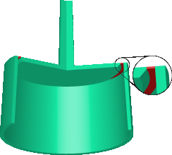
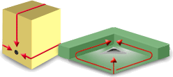
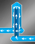
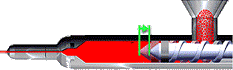
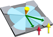
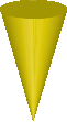
- Dominant flow path
-
The flow path of least resistance (the smallest pressure drop) from the polymer injection location to the last place to fill.
The dominant flow path is normally, but not always, the longest flow path. In the following image, the cone indicates the injection location and the X indicates the last place to fill.

- Drooling
-
Leakage of polymer from the nozzle, sprue, or gate.
Drooling creates thin strands of plastic that can get caught in the mold.
- Dwell
-
A pause in the mold closing cycle of a compression molding operation to permit gas to escape from the molding material.
- Edge gate
-
A gate located on the parting line of the mold.
An edge gate typically fills the part from the side, top, or bottom.

- Ejection
- The removal of molded parts from the mold by mechanical means, or with compressed air.
- Ejection temperature
-
The averaged temperature of the part at the time it is ejected from the mold.
Eject a molded part only when it has enough strength to undergo the force of ejection without excessive warpage or marks from ejector pins. The ejection temperature depends on the resin, part thickness, application, and shop-floor practice. A part ejected at a higher temperature can reduce the cooling time, but can increase warpage.
- Ejection time
-
The moment when the mold opens to eject the part.
An ejection time of 42 seconds indicates that 42 seconds elapsed from the moment the mold closed for injection until the moment the mold opened for ejection.
- Ejector pins
-
Pins that are located on the mold and are used to push the part out of the mold when the clamp is opened.

- End of fill
-
Occurs when the polymer has reached the extremities of the mold cavity and the mold is volumetrically filled.
- Extensional viscosity
-
A measure of the resistance of a polymer to stretching forces.
When a polymer flows through a large cross-section to a smaller one, it stretcheslongitudinally, and results in a pressure drop. The extent of this pressure drop depends upon the extensional viscosity of the particular polymer and the severity of the restriction.
Pressure drop due to extensional effects often occurs when a material flows from a large runner into a small gate.
- Family name
-
The name of a family of materials, such as the polycarbonate family.
Each material is a member of a family of materials. The shortened version of a family name is the family abbreviation. For example, PC is the family abbreviation for polycarbonate.
Some families contain subsets, and there is an abbreviation for each subset. For example, TPE, TPO, TPU, and TPR are family abbreviations within the thermoplastic elastomer family.
- Fan gate
-
A wide edge gate with variable thickness, which permits rapid filling of large parts or fragile mold sections through a large entry area.
A fan gate is used to create a uniform flow front into wide parts, where warpage and dimensional stability are the main concerns.

- Feasible molding window
-
A set of process setting limits that define a window-like shape.
For process settings inside the window boundaries, the molding process is feasible; outside the window boundaries, the molding process is not feasible.
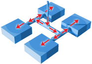
- Fiber orientation
-
The direction of the major axis of the fibers, relative to the flow direction in fiber-filled materials.
In the following image:- Randomly-oriented fibers are found near the injection location.
- Flow-aligned fibers are found in the converging flow area.
- Transversely-aligned fibers are found in the diverging flow area.
- Fibers parallel to the flow direction are found in the restricted flow area.

- Filler
-
Materials that can be added to a polymer for injection molding.
Adding a filler to a polymer can increase the strength of the polymer and help ensure that good quality parts are produced.
- Filling phase
-
The period during the injection molding process when plastic is injected to fill the cavity.
- Filling time
-
A length of time in the injection cycle where the velocity of the machine screw is used to fill the mold.
The filling time starts at the beginning of the injection cycle and ends at the velocity/pressure switch-over point.
- Flash
-
A defect characterized by excessive polymer material escaping from the mold where it separates.
The most common causes of flash are an excessive velocity stroke, injection velocity, packing pressure, and a low clamp force.
Remove flash by either reducing the injection velocity or increasing the clamp force.

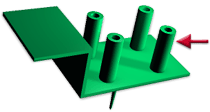
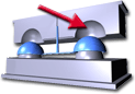
- Flow leaders and deflectors
-
Surfaces with thicknesses designed to direct the flow front, either by attracting it (leaders) or by deflecting it (deflectors).
Flow leaders are thicker parts of the cavity (indicated by the yellow arrow in the following illustration) which attract the flow. Deflectors are thinner parts of the cavity (indicated by the red arrow) which constrict the flow and slow it down.
- Flow path
-
A route along which molten plastic moves within the cavity.
- Friction
-
A force which acts against motion.
Sometimes there is high friction between the part and the mold walls while the part ejects. The part can be impossible to eject, or damage can occur during ejection.
- Gas fingering
-
Occurs during gas injection molding when the gas pressure forces the material outside the designed gas channels to compress too much.
Gas bubbles push their way into part walls forming finger-like branches and can cause structural and aesthetic defects.
- Gate
-
The channel through which the molten polymer flows from the runner into the cavity.
Generally, the gate is small and solidifies first.

- Gate freeze
-
The moment during the packing phase when polymer at the gate has frozen solid and no more polymer can be packed into the mold cavity.
- Gate scar
-
The mark that remains on the surface of the part after the gate has been trimmed; also called a gate-vestige or witness mark.
- Gloss mark
-
Dull surface patches on the glossy or shiny surface of a molded part.
Different flow behaviors of the plastic at the mold wall cause differences in the gloss finish of a part. They are due to different cooling conditions and shrinkage. Dull surface patches can be removed by drying the material, decreasing the injection speed, or increasing back pressure.

- Heat transfer pipe
-
Used in a heat exchanger to improve the heat transfer rate without increasing the pressure loss caused by the fluid flowing through the pipe.
- Heel
-
A feature of an insert, which helps fix an insert to a core or cavity.
- Hesitation
-
The slowing down of the flow front due to preferential material flow through other, less restricted areas of the mold cavity.
In a part with multiple flow paths, the flow can slow down or hesitate in thin regions. This condition enables the melt to cool and in some cases freeze before filling is complete, causing short shots. Flow hesitation is most likely to occur in parts containing thin diaphragms, ribs, and hinges.
- High cushion
-
Occurs when the cushion is too large and the material is kept in the barrel for too long.
High cushion can result in material degradation and cause various defects.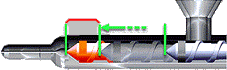
- Holding Phase
-
This phase is made up of the Packing Time and the Cooling Time.
- Hopper
-
The molding machine container that holds the polymer and feeds it to the injection molding screw.
- Hydraulic pressure
-
The pressure applied to the injection ram during the injection phase.
Setting hydraulic pressure is one way of specifying the velocity phase for the molding cycle. The hydraulic pressure is the pressure in the main supply line from the pump, typically measured with a gauge in the hydraulic line. There is a direct relationship between the injection pressure and the hydraulic pressure, called the machine intensification ratio.
- Injection cone
-
The mathematical point at which the Fill analysis begins.
The injection cone is positioned on the surface of the model, at the injection location. When gates and runners are modeled, the effect of shear rate through the gate is taken into account.
- Injection location
-
The place where the molten plastic is forced into the mold cavity.
Different injection locations can have different effects on the appearance and quality of the plastic part.
- Injection pressure
-
The pressure that is applied to the plastic by the ram during the injection phase, causing the material to flow.
You can measure injection pressure approximately using a transducer located in the nozzle. There is a direct relationship between the injection pressure and the hydraulic pressure, called the machine intensification ratio.
- Injection time
-
The time it takes to fill the cavity of the mold with material.
- Injection velocity
-
The speed at which polymer is injected into the mold cavity during the injection phase.
If the injection velocity is too high, it can cause part defects in the plastic part, such as flash and delamination.
- Injection volume
-
The amount of polymer injected into the mold cavity during the velocity phase.
- Insert
-
A component that is placed into the mold before the injection phase. It is anchored into the plastic part by being partially or wholly surrounded by the injected plastic.
Inserts can have threads, can be electrically conductive, or can be a different plastic material.

- Insert sketch
-
A 2D sketch created by the Manual Sketch command.
Profile loops are drawn in a 2D sketch and then used to define the shape of an insert.
- Isotropic material
-
A material with properties that are the same in all directions.
There are no directional effects of orientation or crystallinity in an isotropic material.
- Jetting
-
The snake-like stream of polymer melt that occurs when the melt is pushed at a high velocity through restrictive areas such as the nozzle, runner, or gate, into open, thicker areas, without forming contact with the mold wall.
In the jet, contact points form between the folds of melt, creating small welds. Jetting can lead to part weakness, surface blemishes, and internal defects.

- Juncture loss
-
The pressure drop observed when the melt passes through contractions in the feed system.
Juncture loss occurs between the sprue, runners, and gates.
- Laminar flow
-
Occurs when a fluid (such as water) moves slowly, with fluid particles following straight-line paths parallel to the channel or walls.
Laminar flow is defined as a flow with a Reynolds number of less than approximately 2300. Reynolds numbers greater than 2300 indicate turbulent flow.
- Lifter
-
Angled mold components that enable the release of undercut sections of a plastic part.
The lifter is attached to the ejector plate. As the ejector plate moves forward, the lifter travels along the angled channel. It releases the undercut when enough clearance is generated.
- Lifter angle
-
The included angle between the part core blade and the Z axis.
- Loop
-
The group of connected curves that form a complete boundary of a surface.
- Machine intensification ratio
-
The relationship between the injection pressure and the hydraulic pressure.
The machine intensification ratio is the ratio of material pressure in front of the screw compared to the oil pressure in the piston of the injection molding machine. The typical ratio is 10 and the range of the ratio is usually between 7 and 15.
The machine intensification ratio can be calculated by dividing the piston area by the screw area.
- Master batch
-
A high concentration of pigments, fillers and/or additives that are added to a carrier polymer (carrier resin).
The carrier polymer is added to the raw polymer to form the final compound during the manufacturing process.
Master batches help to ensure that the additives are evenly dispersed throughout the final compound. They also reduce the number of individual materials that manufacturers must purchase and combine to create the compound.
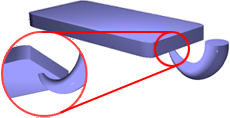
- Meld line
-
A weakness or visible flaw created when two or more flow paths meet and converge while filling a plastic part.
Meld lines can be caused by holes or inserts in the part, multiple injection gates, or variable wall thickness where hesitation or race tracking can occur.
Parallel flows typically form a meld line. Flows meeting at higher angles, often head on, form Weld lines.
Note:
The Weld and meld lines result in theStudy Tasks
pane do not always show meld lines if the model mesh is too coarse.Meld lines tend to be less weak than weld lines. The material type, the type and number of fillers, and the pressure and temperature at the meld line affect the quality of the meld line.

- Melt density
-
A single point density value of a polymer at its average processing temperature, and at zero, or near zero, pressure.
- Melt temperature
-
The temperature of the polymer as it starts to flow into the mold.
- Mold
-
A series of machined steel plates containing a cavity or cavities into which molten plastic is injected at high pressure: also called a die.
The mold also acts as a heat exchanger in which the molten thermoplastic solidifies to the shape defined by the cavity.

- Mold base
-
A fundamental assembly in mold design consisting of several mold plates and standard components.
- Mold open time
-
The period of time the mold is open.
Mold open time begins when the mold opens for the ejection of the plastic part. It ends when the mold closes so that the screw can begin moving forward for injection.
- Mold opening direction
-
The direction of travel for the moving half of the mold.
The plastic parts are ejected in the direction of the mold opening. Mold Design needs a consistent coordinate system to fix components. The opening direction of Mold Design is the positive Z axis.
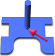
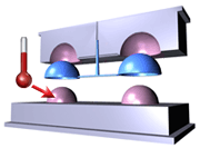
- Mold temperature
-
The temperature of the plastic-metal interface or the mold surface temperature inside the mold.
Different mold temperatures for the cavity and core sides of the mold can mitigate unbalanced cooling or warpage problems.
The arrow in the following image shows the plastic-metal interface.
- Molding window
-
If molding conditions fall within this region, then a good part can be made.
Defines the limits of molding conditions under which an acceptable part can be produced; also called a process window.
The following graph shows a good quality part (labeled with a checkmark), encircled by the boundaries of the molding window. A poor quality part (marked X), is outside the molding window.
- Multi-cavity mold
-
A mold with two or more mold impressions; a mold that produces more than one molding in one molding cycle.
- Network runners
-
Runners in which the flow front splits, and then comes back together; also called looped runners or runner loops.

- No-flow temperature
-
The temperature at which a polymer ceases to flow inside the mold cavity after injection.
- Nominal part thickness
-
The intended wall thickness of the part as a whole.
This value is usually the wall thickness across most of the part. Ideally, the nominal thickness does not vary by more than ten percent across the part. Some design features, such as a boss or a hinge, can be thicker or thinner than the nominal thickness, but these variations are local.

- Non-return valve
-
A valve is located in front of the injection screw on an injection molding machine.
A non-return valve allows material to flow in one direction and closes to prevent backflow.
- Normalized thickness
-
A measurement of part thickness.
The normalized thickness value ranges from -1 to 1. In this range, 0 is the center of the part and 1 and -1 are the plastic/metal interfaces, or mold walls.
- Nozzle pressure
-
The pressure applied to the polymer at the nozzle.
Setting nozzle pressure is one way of specifying the injection pressure of the polymer.

- O-ring
-
A loop of elastomer with a round, o-shaped cross-section, which is used as a mechanical seal or gasket.
O-rings are seated in a groove and compressed between two or more parts during assembly, creating a seal at the interface.
- Open loop controller
-
A type of controller that does not have a feedback loop and does not respond to measurements of the value being controlled.
- Optimization
-
The process of finding the best conditions for molding a particular plastic part.
The part geometry, the material selection, the injection location, and the processing conditions can all be optimized.
- Orientation
-
The alignment of polymer molecules during shear flow
Polymer molecules align themselves in the direction of flow. The extent of this orientation depends on the shear rate to which the material is subjected and the temperature of the melt. When the material stops flowing, the induced molecular orientation begin to relax at a rate dependent on the relaxation time and temperature of the material. If the material freezes before relaxation is complete, the molecular orientation is frozen in.
Frozen-in orientation affects the mechanical properties of the material and also the shrinkage in the direction of material orientation. For a given element, the mechanical properties and the amount of shrinkage are different in directions parallel and perpendicular to the direction of material orientation.

- Orthotropic material
-
A material that consists of either oriented fibers or oriented polymer chains.
In an orthotropic material, mechanical properties in the direction parallel to the orientation are different from properties in the perpendicular direction.
- Over packing
-
Caused by extra material being compressed into one flow path while other flow paths are still filling; generally occurs in sections with the shortest fill time.
Over packing can cause warpage, flashing, and excessive cycle time and part weight.

- Packing phase
-
This phase comprises the packing time and the cooling time.
- Packing time
-
A length of time in the injection cycle that starts when the mold is filled and ends when the packing pressure is released.
- Parting diagnostic
-
A function that checks whether the parting surface has completed, and checks the core faces or cavity face.
- Parting plane
-
The surface of the two mold halves that separates when the mold opens.
- Pinpoint gate
-
A small gate, generally 0.75mm or less in diameter.
To fill all cavities at the same time in multi-cavity molds, the dimensions of pinpoint gates must be held within tight tolerances . Pinpoint gates leave only a small, easily removed mark on the part. But the melt tends to freeze earlier and a third plate is often required for part removal. Pinpoints gates can also lead to high shear rate and high entrance pressure loss.
An indirect gate is a variant of a pinpoint gate. Indirect gates are used when the injection location must be transferred from the center of the part.
- Placement plane
-
The plane that determines the position of the bottom of the lifter assembly.
- Placement reference point
-
A reference point or edge that is parallel to the XY work plane of the mold base assembly. It defines the relative position relationship.
The selected point or edge has the same height as the XY work plane in the mold base assembly in the Z coordinate of the main assembly.
- Plastic part direction
-
The normal direction of the parting surface.
Because plastic parts are built randomly, the direction of the plastic part is also random. Mold Design must adjust the direction of the plastic part to align with the opening direction.
- Plastication
-
The process in which raw material is changed to melt and pushed to the front of the screw through a rotational action.
- Poisson's ratio
-
A ratio (v 12 ) that pertains to a material under tensile stress.
The ratio of lateral or transverse contraction strain (in the second principal direction) to the longitudinal strain (in the first principal direction).
- Polymer
-
A natural or synthetic compound, usually of high molecular weight with a long-chained structure that consists of repeated linked molecular units called monomers or mers.
Monomers are relatively light and simple. A chemical polymerization process builds polymers from monomers.
Although the term plastics is often used as a synonym for polymer, plastics are actually one type of polymeric compound. Plastics are formulated with plasticizers, stabilizers, fillers, and other additives for processing and performance.
Non-plastic polymeric systems include rubbers, fibers, adhesives, and surface coatings.
Processing polymers into end products involves physical changes such as melting and solidification for thermoplastics or chemical reactions for thermosets.
- Preferred molding window
-
A set of boundaries that define an optimal processing window or set of processing parameters represents a refinement of a feasible molding window.
Outside the window boundaries, it can be feasible to mold the part, but the process is not optimal.
- Pressure gradient
-
The pressure drop per unit of length along the flow path.
The pressure drop from one location to another is the force that pushes the molten polymer to flow during filling. Polymer always moves from higher pressure to lower pressure, akin to water flowing from higher elevations to lower elevations.
Filling with a more uniform pressure gradient is desirable. Non-uniform pressure gradients often indicate problems, such as flow hesitation, over-packing that results in flash, and under-packing that results in excessive shrinkage.
- Pressure phase
-
The period during the injection molding process when the machine screw is used to apply pressure to the melt to pack the cavity.
- Pressure profile
-
A graph made up of set points joined by lines.
The set points determine the pressure to apply at specific time intervals. The pressure profile controls how the part is packed out during the pressure stage of a cycle.

- Pressure stroke
-
The proportion of the total stroke performed under pressure control.
Pressure stroke is the distance between the velocity to pressure change-over position and the screw forward position in an injection molding machine.
- Pressurization phase
-
The phase during the injection molding process when extra plastic is injected to ensure all corners and edges of the mold cavity are full of plastic.
- Process control
-
The monitoring and correction of injection molding machine process parameters to ensure the production of a good part.
- Process parameters
-
The variables that typically correspond to molding machine settings.
Commonly used process parameters include:- Maximum injection pressure
- Screw cushion
- Pressure stroke
- Cycle time
- Charge stroke
- Mean injection pressure
- Processing conditions
-
The variables that control the molding process.
Processing conditions include:- The injection velocity
- The pressure applied to the melt
- The mold and melt temperatures
- The material grade being used
- Production run
-
A series of parts made under a particular set of process conditions, for example, a particular ram speed and set of pressure profiles.
- Pull direction
-
The direction that the lifter assembly moves along.
If a planar surface or plane is selected, the selected surface is assembled flush with the YZ plane of the lifter assembly.
If an edge is selected as the pull direction, the positive direction is from the start point to the end point of this edge. The point nearest the cursor is the end point. A vertical work surface is created with the selected edge in the end point. This vertical work surface is assembled flush with the YZ plane of the lifter assembly.
- Purging
-
The cleaning of one color or type of material from the injection molding machine.
You can force out the material with a new color, a new material, or with another purging material.
- Pressure-Volume-Temperature (PVT)
-
Data that describes the specific volume (1/density) of a material as a function of temperature and pressure.
PVT describes the temperature/pressure relationship for polymers over the entire processing range.
- Racetrack effect
-
Occurs when molten plastic flows into thicker regions more easily than thin regions.
The flow divides and then fills thicker sections before combining again to fill the thinner sections. The recombined flow can reverse to meet the oncoming flow in the thinner section.
The racetrack effect can cause air traps, weld lines, and regions of high internal stress.
- Radiate runoff surface
-
A method of creating runoff surfaces.
First an edge is selected and then directions are set to the start and end points of the edge. To improve the surface quality, a point can be added to the selected edge and a direction can be set to the point.
- Ram
-
The part of the injection molding machine that pushes the polymer into the mold, also called the screw.
- Ram speed profile
-
Used to vary the ram movement during the filling phase of the injection cycle.
The ram speed profile plot is made up of set points joined by lines. The set points determine the ram speed to use at specific displacement measurements of the screw during injection.
- Record groove
-
A surface defect with an appearance that is like the grooves on a record.
Record grooves are formed when a high flow resistance exists in the mold, which leads to a repeated temporary stagnation of the flow fronts.
To prevent this defect, increase the mold and melt temperatures while decreasing the injection time.
- Rectangular gate
-
A gate commonly used with two-plate tools; also called an edge gate.
It can be straight or tapered going from the runner to the part.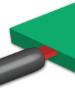
- Rectangular runner
-
Runners with a rectangular cross-section.
Rectangular runners are not recommended because of the high surface-to-volume ratio and restricted flow area.
Rectangular runners have no draft and the ejection of the runners is difficult.
- Region
-
An area or selection of adjoining or connecting entities that can include both planar and non-planar surfaces.
The boundary lines of a region can be curved or straight. Fully connect these lines, and do not intersect them.
- Relative ram speed profile
-
Used in the design stage when an injection molding machine has not been selected.
You can use the geometry of the part, runner system, and the gate with a speed profile and injection time to analyze peak flow rate, maximum injection pressure, and clamp force. The selection of an injection molding machine is based on the results of this analysis.
- Restricted gate
-
A small opening between the cavity and runner in an injection mold.
The gate breaks cleanly after each part is made to assist part recovery.
- Reynolds number
-
The Reynolds Number is a ratio that defines the rate of fluid flow in pipes. It characterizes the particular flow regimes that can occur in the circuit.
The onset of turbulence in water is between 2300-4000. A Reynolds number of 4000, or higher, represents turbulent flow, and turbulent flow is preferred for cooling applications. However the higher the Reynolds number in the circuit, the more energy is required to pump it through the circuit. Hence the ideal Reynolds number for cooling circuits is 10,000. The pumping losses associated with Reynolds higher than 10,000 outweigh the heat transfer gains that can be achieved with higher Reynolds numbers.
- Rib
-
A long, thin intersecting wall that is used to reinforce the outer walls of the plastic part.

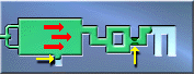
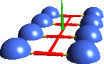
- Runner and Runner system
-
The channels that feed the polymer from the sprue to the gates of each cavity in the mold.
A runner system includes:- Runners, shown in red.
- Sprue , shown in green.
- Gates, shown in yellow.
- Runoff loop
-
The loop along which the core and cavity is split.
Generally, the runoff loop is on the maximum project surface along the pull direction.
- Runoff surface
-
The surface on which the core and cavity meet.
- Screw
-
The part of the injection molding machine that pushes the polymer into the mold.
The screw is the shaft that rotates within the barrel of the injection molding machine to process and prepare the material for injection. - Screw back position
-
The position that the screw is brought back to before the start of the next cycle.
- Screw displacement
-
The distance the screw has moved during the injection phase.
- Screw forward position
-
The furthest position forward the screw achieves during a cycle.

- Screw velocity
-
The speed with which the screw moves during the injection phase.
- Semicircular gate
-
A gate with a half-round cross section.
Avoid semicircular gates because they lead to high fill pressures.
- Semicircular runner
-
Type of runner that can be considered when a circular approach is not possible.
Avoid Semicircular runners because they have a poor volume to surface ratio leading to high fill pressures.
- Semicrystalline
-
A plastic in a mixed state of crystalline and amorphous conditions.
Most plastics are semicrystalline. The crystalline content determines the physical properties or the part.
- Set points
-
The defining points on the ram speed and pressure profiles.
For the ram speed profile, it is a discrete injection velocity and time/displacement coordinate. For the pressure profile, it is a discrete injection pressure and time/displacement coordinate.
- Shear
-
A type of deformation caused by friction between the moving plastic and the mold wall.
- Shear heating
-
The creation of heat as a result of shear stress in flow; also called frictional heating
Friction between adjacent laminae moving at different speeds causes shear heating. The layers of the melt nearer to the wall to attain a higher temperature than the core. This effect can be used to advantage in the design of thin walls of parts where premature freezing is a risk.
- Shear rate
-
The rate of change of shear strain with time.
- Shear strain
-
The ratio of the deformed state compared to the original state, when a polymer has been deformed due to an applied load.
- Shear stress
-
Stress caused by friction between the moving plastic and the mold wall and between the layers of plastic moving at different rates.
High shear stress can cause the plastic to degrade or to fail, due to stress cracks.
- Shell
-
A group of connected surfaces that form an open shell.

- Short shot
-
The incomplete filling of a mold cavity which results in the production of an incomplete part.

- Shot size
-
The distance between the screw back position and the zero screw position of an injection molding screw; also called charge stroke
Shot size is a measure of the polymer available for injection for each part. - Shot weight
-
The mass of plastic delivered in one complete filling of the mold, including the molded parts, sprue, runners, and flash.
- Shrinkage
-
The reduction in the dimensions of a plastic part, compared with the mold dimensions.
Shrinkage occurs as the polymer cools and can vary in different directions.
Crystalline and semi-crystalline materials are prone to thermal shrinkage; amorphous materials tend to shrink less. The causes of excessive shrinkage are:- Low injection pressure
- Short pack-hold time or cooling time
- High melt temperature
- High mold temperature
- Low holding pressure
- Side core
-
A part of the mold that fills an undercut during the injection phase.
Undercuts are features of the finished plastic part that impede the ejection of the part from the mold. A typical undercut is a recess or hole that is not orientated in the direction of the parting plane. After the cooling phase of the injection cycle, the side core is retracted allowing the part to be ejected.
- Sink mark
-
A visual defect on the surface of a molded part.
A differential in volumetric shrinkage causes sink marks. They can occur on the opposite sides of surfaces to which ribs or bosses are attached. They also occur in thicker areas of parts where the volumetric shrinkage is not adequately compensated during the packing phase.
- Specific heat
-
The amount of heat required to raise the temperature of a unit mass of material by one degree Centigrade.
Specific Heat (Cp) is a measure of the ability of a material to convert heat input to an actual temperature increase. This is measured at zero pressure and a range of temperatures, or averaged across the temperature range of 50 C to the maximum processing temperature of the material.
The unit of measure for specific heat is J/kg-C, joules per kilogram Celsius.
- Spiral core
-
A core with a spiral-shaped channel.
A spiral core enables fluid to flow through it and carry away the heat.
- Sprue
-
The main feed channel through which polymer flows from the molding machine nozzle to the runner system, or directly to the part.

- SSORCG solver
-
Symmetric Successive Over-Relaxation Conjugate Gradient; a type of iterative matrix solver used in warpage calculations.
- Start of fill
-
The time at which melted polymer starts to flow.
The start of fill happens after the screw has started to move and corresponds to the start of the pressure rise in the nozzle.
- Stop pin
-
A metal pin that is used to prevent the rotation of a core pin.
- Streak mark color
-
Usually occurs because of different orientation of the pigments in the flow, or poor blending in the plastication stage.

- Streak mark dark
-
Thermal damage to the material during filling, or inadequate tool venting can cause dark colored brown or silver streaks.
To avoid dark streaks, rectify the venting system, or reduce the injection speed or pressure.
- Streak Mark Glass Fiber
-
Rough and matt streaks caused by differential shrinkage or premature freezing of glass-filled material against the mold wall.
To avoid glass fiber streak marks, use shorter glass fibers, increase the melt temperature, or increase the mold wall temperature.
- Streak mark white
-
Also appear as silver streaks.
Causes of white streak marks are:- Moisture Streaking occurs opposite the flow direction due to a high residual moisture content. Drying the material properly removes this defect.
- Air Air is trapped and cannot escape while the mold is filling. The air is drawn to the surface and stretched in the direction of the flow causing streak marks.

- Stroke
-
The distance between the screw back position and the screw forward position of an injection molding screw.
The stroke provides a measure of the amount of polymer injected during a cycle.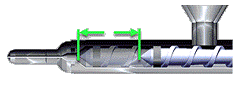
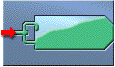
- Suck back
-
A technique used to clear polymer from the injection nozzle by moving the screw away from the nozzle; also called decompression or pull back.
- Switchover
-
Designates the transition from one phase to another, for example, the transition from the filling phase to the packing phase.
You can use various switch-over methods. For example, you can initiate fill-to-pack switchover when the injection time or pressure reaches a specified value, when a specified percentage of the volume is filled, or when other conditions are met.
- Tensile strength
-
The maximum nominal stress sustained by a material being pulled from both ends, at a specified temperature and at a specified rate of stretching.
- Tessellation
-
The repetition of a shape over a plane, leaving no region uncovered.
Squares, triangles, and hexagons tessellate easily.
- Thermal conductivity
-
The rate of heat transfer by conduction per unit length per degrees Celsius expressed in units of W/m. C
Thermal conductivity is a measure of the rate at which a material can dissipate heat. The rate is determined under pressure and averaged across the melt temperature range of the material.
- Thermal Degradation
-
A break down of material quality, resulting in poor parts.
Thermal degradation can occur if the barrel temperatures are too high, rotational speed of the screw is too fast, or the nozzle diameter is too small.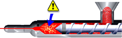
- Thick and chunky
-
A term used to characterize geometry that does not approximate thin-walled shells.
Thin-walled shells have a clearly identifiable thickness (t) that is much smaller than the lateral dimension of the part (L). That is (t) divided by (L) is much less than 1 (t/L <<1). This formula is not true for thick and chunky parts which have significant areas that do not satisfy this condition.
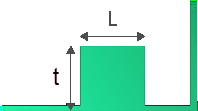
- Tooling noise
-
Caused by molding problems toward the end of the velocity phase when the injection pressure is too high.
Excessive tooling noise can lead to tool damage.
- Transducer
-
A mechanical or electrical device to measure a value. It transmits the measurement to a recorder, or to a device that can compare the measurement to a desired value.
- Transition temperature
-
The polymer freeze temperature at which the melt-to-solid transition occurs.
The transition temperature corresponds to the glass-transition temperature (Tg) for amorphous materials and to the crystallization temperature (Tc) for semi-crystalline polymers.
- Trapezoidal Runner
-
Runners used in place of circular runners when cutting runners on both sides of the parting line is difficult.
Three-plate tools, and two-plate tools with slides are situations in which a trapezoidal runner is used.
- Turbulent flow
-
Type of flow that occurs when a fluid (such as water) flows with fluid particles experiencing erratic variations in direction and speed.
Turbulent flow is defined as a flow with a Reynolds number greater than 4000. Low Reynolds numbers indicate laminar flow.
- Unbalanced flow
-
Type of flow that occurs when polymer melt completely fills some flow paths in the mold before other flow paths have filled.
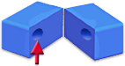
- Undercut
-
A trapped area in a model that cannot be ejected from the mold.
These areas require a slide, which usually slides in a perpendicular direction to the core and cavity segments as these areas are separated. In the following image, the section labeled a is the undercut, and the section labeled b is the parting plane.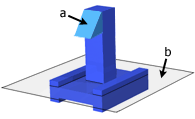
- Underflow
-
Occurs when flow fronts from two directions meet, then pause momentarily, long enough for a frozen layer to develop. The polymer in one of the flows then reverses direction and flows back between the outer frozen layers.
When the flow reverses the frozen layer partly remelts due to shear heating. This flow reversal gives poor part quality, both from a surface appearance and structural viewpoint.
To avoid underflow, balance all flows so that their flow fronts meet at the end of fill.
- Unidirectional flow
-
Flow in one direction, with a straight flow front, during the filling phase.
Unidirectional flow is desirable because it improves the mechanical properties and quality of the part. Polymer injection location determines flow direction.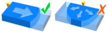
- Valve gate
-
A component of a hot runner system.
The sprues from the hot runner drop through the cavity plate to the parts. Each sprue has a rod that can be moved forward to cut off flow through the sprue. The opening of the sprue is timed to be just after the melt front has passed that location. The lower pressure drop through the hot runner system is passed on to the gate. The results is lower filling pressures and reduction in the number of weld lines in the plastic part.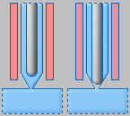
- Velocity stroke
-
The distance between the screw back position and the velocity to pressure switchover position in an injection molding machine.
Velocity stroke is the proportion of the total stroke performed under velocity control.
- Velocity to pressure switchover
-
The position of the screw when the machine switches the screw displacement control from velocity control in the filling stage to pressure control in the packing stage.
- Vent
-
A small channel at the end of a flow path that allows air to escape the cavity.

- Venting
-
A minor modification to the mold so that trapped air can escape.
When air is trapped within the cavity blackening or dieseling of the part can occur.
- Viscosity
-
A measure of the resistance to flow that a material has within a mold cavity.
- Viscosity index
-
The viscosity of the material at 1000 1/s shear rate and at a specified temperature.
For example, VI(240)125 means that the material has a viscosity of 125 Pa.s at a shear rate of 1000 1/s and a temperature of 240 C.
The viscosity index is used to compare the viscosity of one material to another.
- Viscosity model
-
The relationship of the variables that affect viscosity.
The viscosity of polymers is dependent on temperature, pressure, and shear rate. There are several mathematical models that can be used to describe viscosity.
- Voids
-
A defect in the plastic part due to the plastic pulling away from the middle of the part as the molten plastic cools.
Material shrinkage during the cooling phase causes voids. If the part is transparent, a void is a cosmetic defect. If the void is large, it is a structural defect.
Eliminate voids by using proper cavity pressurization in the packing phase.
- Warpage
-
Warpage is a part defect caused by a non-uniform change of internal stresses.

- Weld line
-
A weakness or visible flaw created when two or more flow paths meet during the filling process.
Holes or inserts in the part, multiple injection gates, or variable wall thickness where hesitation can occur can cause Weld lines. If the different flow fronts have cooled before meeting, they do not recombine well, and cause weakness in the molded part. A line, notch, and/or color change can also appear.
The quality of the weld line depends on the material type, the type and number of fillers, and the pressure and temperature at the weld line.
Move weld lines to areas where strength is of less importance and visual appearance is less obvious. Weld lines can be moved by changing:- Gate position and dimension
- Wall thickness
Note: The Weld lines result in the Study Tasks pane do not show all weld lines if the model mesh is too coarse.
- Wire-sweep index
-
A value that represents the force created by the flow of plastic past the wires of an integrated circuit; also called the sweep index.
The wire-sweep index is the sum of the velocity of viscosity time at each grid point in the model. The result is averaged by the number of grid points.
A wire-sweep index that is high in regions of the model containing wires indicates a possible location for wire breakage.
Since viscosity depends on temperature, shear rate, and the rate of cure, you can reduce a a wire-sweep index by changes to these variables.
- Workpiece
-
A software definition to define the outline of the core and cavity.
- Zero screw position
-
The furthest possible forward position of the screw.
The zero screw position is where the end of the screw is in contact with the barrel or hits the machine stops.