Use a symmetry plane to force the generated shape to be symmetric about the plane. Up to three symmetry planes can be used on the model, one for each of the local XY, XZ, and YZ planes. The symmetry plane can either reference an existing UCS or be aligned with the global coordinate system and intersect the center of mass of the part.
Create a Symmetry Plane
- On the Analysis tab > Goals and Criteria panel, click
 Symmetry Plane. By default, the symmetry plane is positioned at the center of mass of the part and aligned with the global coordinate system.
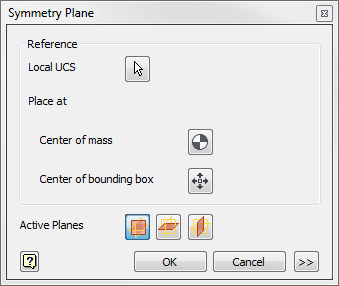
- To align the symmetry plane with a UCS, click the Local UCS button and select an active UCS as the reference for the symmetry plane. The symmetry plane is created in the local XY plane of the UCS.
- Click the Center of mass button if you want to place the UCS and symmetry plane at the center of mass of the part.
- Click the Center of bounding box button if you want to place the UCS and symmetry plane at the center of the bounding box of the part.
- Toggle the
Active Plane buttons to add a symmetry plane in one of the other orthogonal directions.
- Click OK.

Manage Symmetry Planes
After you have created a symmetry plane, you can edit, suppress, or delete the plane by right-clicking the symmetry plane in the browser tree.