Edits properties of drawing views. Specifies a model and setup for a base view.
| Access: |
To create a view, click the Base command on the Place Views tab. To edit a view, right-click the view in the browser or the graphics window, and then select Edit View from the menu. |
Component tab
- File
-
Specifies the source part file to use for the drawing view.
Click the arrow to select from the list of open models, or click Open, and find a model file.
- Representation
- Model State selects a model state to show in the view. Each model state can have unique members and properties in parts lists.
-
Design View lists names of design view representations. Select a view representation from the list. This option is available when the selected file contains defined design view representations. Select the Associative check box to update the drawing when changes are made to the associative design view representation in the part or assembly environment.
Click the View settings icon to set the view representation preferences for the Base view. Available for Base view creation only.
Note: If you enable the options in a Sheet Format, the Design View name and the View name must match exactly. For example, Front is not the same as FRONT.
to set the view representation preferences for the Base view. Available for Base view creation only.
Note: If you enable the options in a Sheet Format, the Design View name and the View name must match exactly. For example, Front is not the same as FRONT.- Check Camera View to use the camera specified in the design view.
- Check Include 3D Annotations to add the annotations included in the design view.
Tip: To extract 3D Annotations for projected views, double-click in the view to activate and then enable Include 3D Annotations in View settings. This displays the 3D Annotations in the view, and sets the view options for inclusion in a sheet format.Note: The Camera View option is disabled when creating or editing a projected view to maintain the relationship between the base view and projected view. Both options are disabled when creating child views when the camera orientation of the child view does not match the orientation of the drawing view being edited.
- Position View selects a positional representation to show in the view. Available for base view creation only.
Available only when the selected file is an assembly document.
- Style
-
Sets the display style for the view.
 Displays hidden lines in the view.
 Removes hidden lines from the view.
 Displays shaded model in the view.
Note: You can control hidden line visibility after drawing view creation using the Hidden Lines command accessed from the context menu of a component. Click the Hidden Lines to toggle between views. Right-click the part or a component in the browser and select Hidden Lines.
Displays shaded model in the view.
Note: You can control hidden line visibility after drawing view creation using the Hidden Lines command accessed from the context menu of a component. Click the Hidden Lines to toggle between views. Right-click the part or a component in the browser and select Hidden Lines.  Style from Base
- Sets the display style of a dependent view to be the same as that of its parent base view. To change the display style for a dependent view, clear the check box.
- Raster View
-
Select the check box to generate raster drawing views. Raster views are pixel based views that generate much faster than a precise view and are useful for documenting large assemblies. After creation, use the context menu to convert a raster view to a precise view, or a precise view to a raster view.
A raster view is framed by a green box in the display. A raster view in the browser is represented by a diagonal red line in the view icon
 .
.
Some commands are not available in a raster view.
- Label
- View Identifier
- Edits the view identifier string in the Format Text dialog.
- Scale
-
When placing a view, sets the scale of the view relative to the model. When editing a dependent view, sets the scale of the view relative to the parent view.
Enter the scale in the box or click the arrow to select from a list of commonly used scales.
Note: You can enter a scale that is not on the list. The new scale appears above a line in the list and is available until you close Inventor.Tip: Edit the standard settings to customize the list of pre-defined scales. On the ribbon, click Manage tab Styles and Standards panel
Styles Editor and then click the current standard. Then add or remove scales in the Preset Values list on the General tab.
Styles and Standards panel
Styles Editor and then click the current standard. Then add or remove scales in the Preset Values list on the General tab.
- Scale from Base
-
Sets the scale of a dependent view to be the same as the scale of its parent view. When selected, the dependent view maintains the same scale as its parent view. To change the scale of a dependent view, clear the check box.
![]() Turns the visibility of the view label on or off.
Turns the visibility of the view label on or off.
![]() Edits the view label text in the Format Text dialog box.
Edits the view label text in the Format Text dialog box.
- The following options depend on the file type:
- Hide small parts
- In large assembly models small components may not be visible in the view, you can turn off visibility of small components based on size.
The document units are used by default. To change the units, click the <icon image here> and select the desired units.
- Sheet Metal View
-
Available only when the selected model is a sheet metal file.
Folded Model creates a view of the sheet metal folded model. Punch and bend annotations are not available for folded model views.
Flat Pattern creates a view of the sheet metal flat pattern. Available only if a flat pattern exists in the sheet metal file.
Bend Extents sets the visibility of sheet metal bend extents in the view. Select the check box to display the bend extents.Note: The appearance of bend extents is determined by the Sheet Metal Bend Extend object default.Punch Center controls if punch centers are included in the view. Punch centers must be recovered to create punch notes or punch tables. Available only if Flat Pattern is selected.
- Presentation
-
Available only when the selected file is a presentation document.
View Specifies the presentation view to use.
To associate the drawing view with the presentation, select the Associative check box above the view list.
Show Trails Shows or hides the trails in the selected presentation view.
- Member
- For an iPart factory, selects the member to represent in the view.
Model tab
- Member
- For an iAssembly factory, selects the member to represent in the view.
- iPart Member
- Selects the sheet metal iPart member to represent in the view. Available only if a sheet metal iPart is selected as the source file.
- Reference Data
-
Hidden Line Calculation specifies whether or not reference data is calculated together with model data for hidden line display.
- Reference Data Separately - reference data is not calculated for hidden line display and is visible through model data (see inside revision cloud).
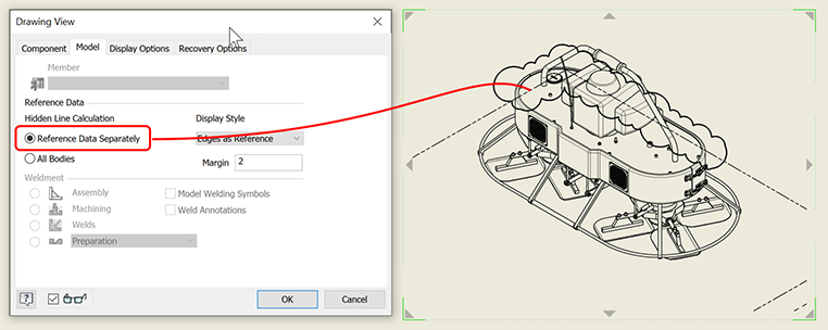
- All bodies - reference and model data are calculated for hidden line display and reference data is hidden by model data (see inside revision cloud).

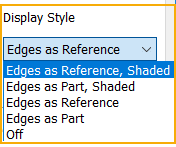
Display Style sets the style for creating shaded views of referenced parts. Click the arrow to make a selection.
 Margin sets the amount of area outside the normal view boundary that the view boundary extends. Controls the amount of reference geometry shown in the view.Tip: Parts with the BOM Structure set as Reference are not included in the formula for creating the default size of the view bounding box. As a result, the Reference parts can be clipped in drawing views. To extend the size of the view bounding box, increase the Margin value.
 - Reference Data Separately - reference data is not calculated for hidden line display and is visible through model data (see inside revision cloud).
- Weldment
- Available only when the selected file contains weldments. Click the weldment state to represent in the view. All components in preparation state are listed below the Preparation separator line.
- Model Welding Symbols
- Associates model welding symbols to the view. Select the check box to get the model welding symbols. Clear the check box to place the view without model welding symbols.
- Weld Annotations
- Associates model weld caterpillars and end fills to the view. Select the check box to get the model weld annotations. Clear the check box to place the view without model weld annotations.
Display Options tab
Only options applicable to the specified model and the view type are available.
- Standard Parts
-
Hidden Lines controls the display of hidden lines for standard fasteners in drawing views of assemblies.
- Never removes hidden lines for all standard fasteners.
- Obey Browser respects the browser setting of the Hidden Lines property for each standard fastener.
Tip: To change the Hidden Lines property, in the browser, expand the drawing view node, and change the setting for specific parts. - Section controls the sectioning of standard parts in the drawing views of assemblies.
- Never Standard parts are never sectioned even when the Section Participation property is set as Section.
- Always Standard parts are always sectioned even when the Section Participation property is set as None in the browser.
- Obey Browser defaults to browser setting. By default, the Section Participation property is set as None for all standard parts.
Tip: To change the Section Participation property, in the browser, expand the drawing view node, and change the setting for specific parts.
- Cut Inheritance
-
Switches on and off the inheritance of a breakout, break, section, and slice cut for an edited child view. Select the check box to inherit the corresponding cut from the parent view.
Note: The available options are determined by the type of the edited view.
- Thread Feature
- When selected, turns on the visibility of thread features in the view. Setting persists until you change it. Off by default.
- Tangent Edges
- Sets the visibility of tangent edges of the selected view. Select the check box to display tangent edges. Clear the check box to hide them.
Foreshortened sets the display of tangent edges. Select the check box to shorten the length of tangent edges to distinguish them from visible edges.
- Interference Edges
-
Enables the visibility of associated drawing views.
When selected, associated drawing views are to display both hidden and visible edges that were previously excluded due to an interference condition (press, or interference fit conditions, threaded fasteners in tapped holes where the hole feature is modeled with the minor diameter).
This option is enabled only when you edit or create drawing views of assembly or presentation files.
- Align to Base
- Sets the alignment constraint of the selected view to its base view. When the check box is selected, an alignment exists. Clear the check box to break the alignment.
- Definition in Base View
- Controls the display of detail circles, section lines, and their associated text. Select the option to display the annotations.
- Orientation from Base
- Specifies camera orientation of a dependent view when base view is rotated or re-oriented. When selected, the dependent view inherits the new orientation from the base view.
Tip: By default, a parent view and its child views keep the same orientation. To break the orientation inheritance, edit the child view, and clear the Orientation from Base box.
- Hatching
- Sets the visibility of the hatch lines in the selected section view.
- Center Justified
- Sets the justification of the view. Click the arrow to select Centered or Fixed. For example, if geometry modifications extend the model to the right, the centered view will adjust in all directions to keep the view centered around it's original position. A Fixed view will update by increasing size in the direction of the geometry modification.
Recovery Options tab
These options define access to surface and mesh bodies as well as model dimensions and work features in the drawing.
- Models of Mixed Body Types
-
Include Surface Bodies controls the display of surface bodies in the drawing view. The option default is unchecked and excludes surface bodies in the drawing view.
- Include Mesh Bodies controls the display of mesh bodies in the drawing view. The option default is unchecked and excludes mesh bodies in the drawing view.
- All Model Dimensions
-
Select the check box to retrieve the model dimensions. Only those dimensions that are planar to this view and were not used in existing views on the sheet display. Clear the check box to place the view without model dimensions.
If dimension tolerances are defined in the model, they are included in the model dimensions.
- Use Work Features
-
Recovers work features from the model and displays them as reference lines in the base view. Select the check box to include the work features.
This setting is used only for initial base view placement. To include or exclude work features in an existing view, expand the view node in the Model browser and right-click the model. Select Include Work Features and then specify appropriate work features on the Include Work Features dialog box. Or, right-click a work feature and select Include.
To exclude work features from the drawing, right-click the individual work feature and clear the Include check box.