Slice through model to display half, quarter, or three-quarter views.
Slice through a model to display a cross-section or interior view without modifying geometry. Use it with parts or assemblies
Section View parameters are stored in a design view representation. Create a design view for every section view you need.
Section View Toolbar
The section view mini-toolbar provides access to the following:
- Flip can be used to invert the cutting plane normal to reveal the cut from the opposite direction.
- Section Plane control provides both Move and Rotate options which you can toggle between to get the cutting plane you desire.
- Value control which provides distance when moving a cutting plane and angle when rotating a cutting plane.
- Cap Preview option to turn off or on the preview.
Create a Half Section
- Click
View tab
 Appearance panel
Half Section View
Appearance panel
Half Section View
 .
.
- Select any plane or planar face as the cutting plane.
- Right-click and select Flip, if necessary, to change the direction of the section or use the displaying tools.
- Drag the plane or enter a value in the field to change the position.
- Click Continue.
- Right-click then select:
- OK to apply the section.
- Flip to change the direction of the section.
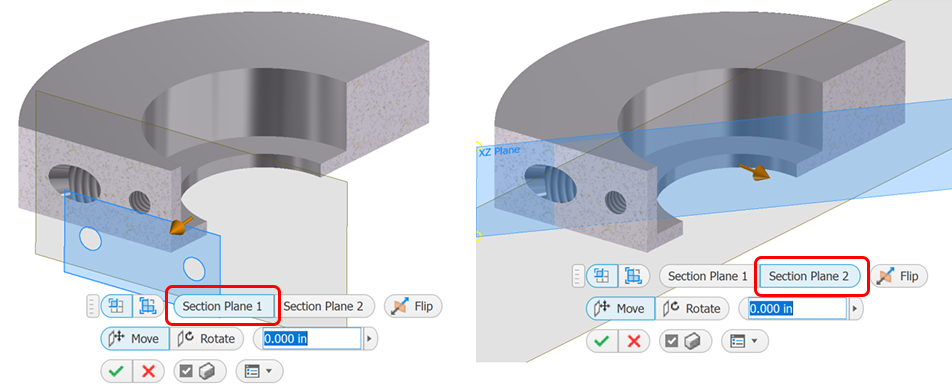
Create Quarter and Three-Quarter Sections
- Click view tab Appearance panel and then select a section view type:
- Quarter Section

- Three Quarter Section

- Quarter Section
- Select any plane or planar face as the first cutting plane.
- Right-click and select Flip, if necessary, to change the direction of the section.
- Drag the plane or enter a value in the field to change the position.
- Right-click in the canvas and click Continue.
- Select any plane or planar face as the second cutting plane.
- Right-click and select Flip, if necessary, to change the direction of the section.
- Drag the plane or enter a value in the field to change the position.
- Right-click then select:
- OK to apply the section.
- Flip to change the direction of the section.
- Three Quarter Section View to change the section view type.
Note: In Inventor, components created from Content Center are not sectioned by default. Check the Section All Parts box on the Assembly tab in the Application Options to section Content Center parts. Click Tools tab
Options panel
Application Options to access the Application Options.
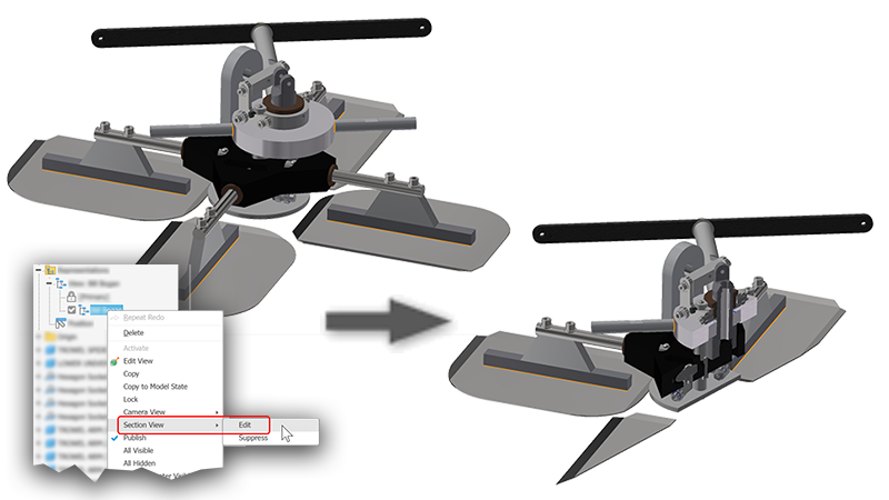
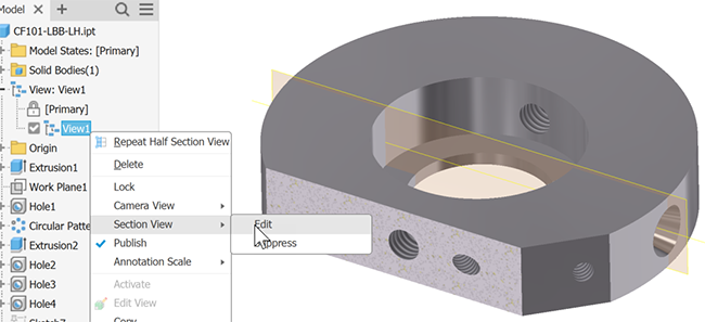
Edit or Suppress a Section View
- In the model browser, right-click the view representation having the section view you want to edit and click
Section View > Edit.
Note: You also have the option to suppress a section view.
- Using the in-canvas tools, modify the section view definition.
- Click OK to apply the view changes.
Delete a Section View
- Activate the view representation having the section view you want to delete.
- Click
View tab
Appearance panel
Delete Section View
 . The model returns to the normal view.
Section Capping
End cap visibility is set by default to display end caps for sectioned geometry when the part count is <= 500. If the part count is >500 the end caps do not display. You can override the setting by selecting or deselecting the option in the mini-toolbar.
Modifying the Section Capping Plane Texture
Use your own texture image for the capping plane texture or color. Capping plane texture images are scaled for each part in an assembly.
- Use the image editor of your choice to create a texture or color BMP image. It must be BMP format. Save the image to a disk location
- In Inventor, click
Tools tab
Options panel
Application Options
Color Tab.
- In the Section Solid Texture dropdown list select Bitmap Image.
- Click the file browse button, then, navigate to and select the texture image you want to use.
Controlling the Scroll Wheel Step Size
You can specify an incremental value that is applied when you roll between scroll wheel detents during the section view command. For a move action the units are linear, for a rotation action, the units are degrees.
- Start the Section View command.
- Right-click in the display and in the context menu, click Virtual Movement Scroll Step Size.
- In the dialog, specify the distance value used by the scroll wheel as you roll it.
- Click the green check to close the dialog box. Subsequent mouse wheel rolling uses the specified value.