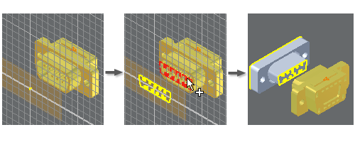
In Inventor, you can project geometry from existing objects onto the active sketch plane.
What's New: 2024.2

You can project edges, vertices, loops, work features, or other sketch geometry. Projected geometry is associated with (linked to) the original geometry, so if the original geometry changes, the projected geometry updates accordingly. (Projected geometry is also called reference geometry, because it is simply a reference to the original.) For example, a rectangular projection of a slot inherits changes to a fillet on the parent slot.
Reference geometry can be created in multiple ways:
- When you create a sketch on the planar face of a model, all edges of the face are automatically added to the sketch as reference geometry.
- The Project geometry command projects model edges, vertices, work features, points, or curves from a visible sketch onto the active sketch plane as reference geometry.
Tip: When the Construction geometry toggle is off, press shift and click the geometry you want to project as construction geometry. This also works when the Construction geometry toggle is on, press shift and click the geometry you want to project as sketch geometry. This works in both 2D and 3D sketches.
Note: Reference geometry created by projection can be deleted, but reference geometry automatically inferred when you sketch on a model face cannot be deleted.
Projecting is useful when working in a top-down assembly design because it saves you from manually updating and positioning repeated parts. You can also use projected geometry to:
- Add a silhouette to the sketch plane for use in a profile or path.
- Project a sketch from a feature onto the sketch plane to use in the profile or path of a new feature.
- Define the boundary for a break-out view in a drawing.
- Copy model edges and 2D sketch geometry into a 3D sketch.
- Constrain or dimension sketch curves or points, such as projecting the default center point onto the sketch plane to constrain the sketch to the origin of the coordinate system.
Reference geometry updates to reflect changes in its source feature, so that the projection of the geometry onto the sketch plane is correct. For example:
- If edits to a source feature create additional vertices or edges, they are added to the reference geometry.
- Lines that split or merge in the source feature behave as one line in the reference geometry.
- Changes in draft angle or depth of extrusion in the source feature also reposition reference geometry.
- If an edge of a source feature is trimmed, the sketch that refers to that edge resizes to the new length.
- If reference geometry is based on a feature that is then deleted, the reference geometry loses its association to the original feature and is converted to fixed sketch curves. Constraints and dimensions are preserved.
A few things to consider when working with projected geometry:
- You can break the association between original and projected geometry and then use any sketch or constraint command to edit the original or projected geometry independently.
- You can automatically project sketch geometry by clicking Tools > Options panel > Application Options, and in the Sketch tab of the dialog box, select Autoproject Edges During Curve Creation.
- The size and position of projected geometry is fixed relative to the originating sketch. You can constrain sketch geometry to the projected geometry.
- Projecting spline curves from the construction environment to a 2D sketch creates non-associative reference splines. Any edits to a reference spline create an approximation of the original spline, which can reduce the accuracy of the curve.
- You can project the edges of a component cut by an assembly section to the sketch plane if the part would intersect the sketch plane. Projected cut edges are not associative in a sketch. The geometry is a “snapshot” of the geometry when projected, and if the parent geometry changes, the projected geometry does not update.
- When you project all of the loops on a part face, changes to the parent feature or face, such as causing the loops to overlap, automatically trims the projected loop. If the geometry is projected one curve at a time instead of a loop, the projected geometry isn’t trimmed.