What's New 2023.1
Use general annotations and notes to add 3D annotations to a part or assembly.
In a part file, use the Tolerance Feature command and the General Profile Note to add Geometric Dimensioning & Tolerancing (GD&T) and other manufacturing information to the model.

GD&T annotations on the 3D model describe the tolerances, controls, and allowable variation in the model. The term Model-Based Definition (MBD) refers to a fully defined 3D model. The annotated 3D model is often sent directly to manufacturing to create the physical part.
GD&T describes the following controls for features in the model:
- Form control such as Flatness
- Profile control such as the Profile of a surface
- Orientation control such as Perpendicularity
- Location control such as Position
- Run out conditions
Use commands available on the Annotate tab in a part or assembly file to add 3D annotations to your model.

Use the Tolerance Feature command in a part file to add GD&T annotations to your model. Use the Tolerance Advisor to help you understand the state of your model and manage the Tolerance Feature annotations.

Workflows and user interface for 3D annotation commands are like annotation commands in the drawing environment. For example, after you place an annotation or click OK in a dialog box, you can continue adding symbols of the same type.
Setting 3D annotation units and standards
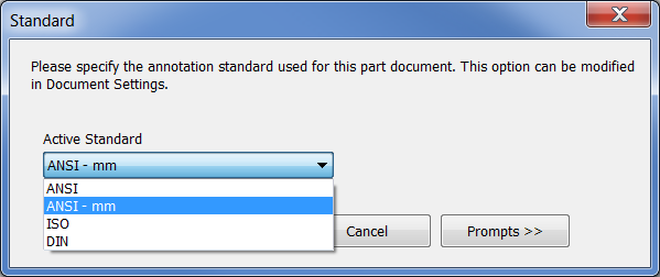
Changes to Document Settings Units tab do not affect 3D annotations. Click Document Settings Standard tab and then specify the Active Standard to set the units. If no active standard exists the first time you use a 3D annotation command, you are asked to choose a standard.

Set the view annotation scale
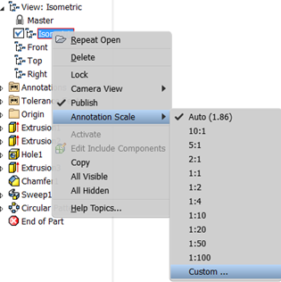
The scale of 3D annotations is independent of the Annotation Scale option in the Application Options > General tab and can be a different size in each view. Right-click a view in the browser and select Annotation Scale to set the scale.

You can also control the annotation scale of the active view by selecting the Annotation Scale drop-list in the Annotate tab > Manage panel. Use the Auto setting to let the system control the size, or choose Custom to define a scale not available in the list.
3D annotations and tolerance features in the browser
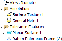
A browser folder lists all Annotations (parts and assemblies) and Tolerance Features (parts only) in the file. Cross highlighting between the graphics window and the browser is available for the annotations and tolerance features.

Use View representations to control annotation visibility and scale
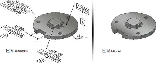
Set the visibility and scale of model annotations specifically for each design view and then save the current camera. By default, when you create annotations in the active design view, the annotations are added to all existing unlocked design views.

The scale of 3D annotations is independent of the Annotation Scale option in the Application Options > General tab. Right-click a View representation to set the Annotation Scale.
- In the View tab, use the 3D Annotations Object Visibility filter to toggle all 3D annotations on and off.
- In the Quick Access Toolbar, use the Select Annotations filter to select only 3D annotations to manage visibility in view representations. For example, make the Top view active and then turn off the visibility of annotations that should not appear in the top view.
- Create section View representations to detail internal features.
- Reorder annotations in the browser, using drag and drop, for better annotation organization.