The utility model provides basic utility network components, which are used in the utility applications, such as Water, Gas and Wastewater. It splits the network geometry (connectivity) from the attribute data.
The utility network consists of nodes and edges that represent the connectivity. The utility model stores this network in one point feature class (nodes) and one line string feature class (edges) and relates the geometry to the different utility objects (attribute data). When you create a utility model, you choose to create the appropriate logical (network) topology at the same time.
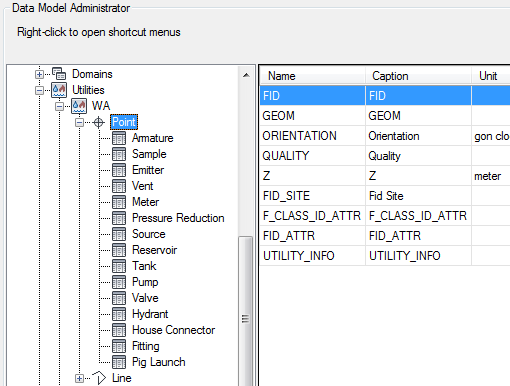
Example: In the Water application, the utility node feature class has a multi-relation to all point attribute feature classes, such as armature, emitter, vents, meters and so on. The utility edge feature class has a relation to the line attribute feature class Pipe.

Utility data model: Water node feature class Point with its relations to the object feature classes; shown in the data model explorer.
This structure is not displayed to the user. However, the user can digitize the attribute feature because of special utility feature rules. Then the geometry features are processed.
The concept of separating geometry and attribute storage allows for two different line splitting methods, soft and hard split. These methods determine how the system deals with the attribute data of the two resulting features.
- Soft Split—The line is split into two separate features. Each has its own geometry, but both use the same attribute data.
- Hard Split—The line is split into two separate features. Both have their own geometry and both have their own attribute data.
For more information about the utility applications refer to the respective Application Guides, such as the Water User Guide.