To convert data to industry model features
- In AutoCAD Map 3D toolset, switch to the Maintenance workspace.
- Open a project or an industry model template or file.
The current industry model will be the target for the converted data.
 – Click
.
- In the
Convert to Industry Model dialog box, under
Source Data, click any of the following:
 –
Add File-based Sources. Use this option to convert data from DWG, SDF, SHP, and SQLite sources to design features.
 –
Add FDO Connection Sources To Convert. Use this option to convert data from an FDO connection to design features. You must first connect to the source using
.
 –
Add Industry Model Sources To Convert. Use this option to convert data stored in previous versions of
AutoCAD Map 3D toolset. In this case, minimal mapping is needed.
 – After adding the source data and assigning an industry model, you can expedite the data mapping process by clicking the
Automatic Mapping button.
Feature classes and their properties may not always have logical names. The mapping process allows you to set logical names that are easier to understand. For example, instead of using the feature class name like EL_OH_CONDUCTOR, it could be mapped as Conductor.
- If you have saved a mapping profile, at the bottom of the
Source Data list, click
Load and specify a saved mapping profile.

- Select and clear mapping check boxes as desired and click
Convert.
You can select multiple sources to convert.
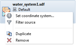
Tip: Right-clicking in the source data column of the Data Mapping area opens a menu where you can choose to select or deselect all features and properties. - To apply a filter to the source data, right-click the data source and click
Filter Source.

- If necessary, you can change the coordinate system assigned to the source data. Right-click the source and click
Set Coordinate System.
Note: You must specify the original coordinate system for the data. Do not specify the coordinate system for the target drawing. AutoCAD Map 3D toolset transforms the data to the target coordinate system when it adds it to your design.
- In the
Data Mapping area, define the mapping between items in the source data and feature classes and attributes in the industry model data model.
If the source is DWG, you can create mappings from layers, entities, or blocks, to corresponding feature classes in the industry model. From the drop-down list, select Entity, Block Name,Layer, or Object Data.
To create mappings between particular attributes, click the attribute of interest in the source list, then click the drop-down list in the All Models column.
You can specify how attribute values in the source data map to values in the design. For some attributes, you can use the Expression Builder when mapping attribute values. For example, you can convert units, perform calculations, or concatenate values in the source when mapping to attribute values in the design. For DWG files, you can map colorindex, linetype, and lineweight values in the source data to the appropriate values in the design drawing. For example, linetypes in a DWG might represent conductor models in the design drawing.
- When you have completed the mapping for a source, you can save the mapping as a profile. You can later reload the profile for future conversions. From the dropdown at the bottom of the Source Data list, click Save.
- To validate the connectivity of features and run design validation rules, select
Reinitialize and Validate Topology.
This option will display any connectivity and rule errors encountered in the Topology Checker palette when the source data is converted.
Note: This option purges and then recreates all topology information for the topologies affected by the conversion process. For example, for an enterprise database with 100 connected users, using this option drops the connectivity for all users and then initializes the connectivity with default values. Connection directions and special connections are lost. Any customized information (for example, flows) are reset to their default values. If you use this option, connected users should disconnect first, as their work may be interrupted. - When you have finished creating the mapping between the source and the industry model, click
Convert.
Only mapped items are converted. If you do not want to convert a mapped item, clear the checkbox for that item.
Next workflow: Setting Up Display Models