The Create Schematics command creates the schema plan template that comprises the schematic feature classes, and rules how to derive the schematic features from the real world features.
To create a schema plan template
- In the Infrastructure Administrator, do one of the following:
- Click Enterprise and connect to the enterprise industry model . Open a project.
- Click File and open a project.
- Expand the industry model node.
- Start the data model administrator.
- Right-click the Representations node, and click Create Schematics.
- Specify the properties as shown in the following table.
- Click Create.
|
Create Schematics |
Description |
|
General area |
Specifies general settings. |
|
Schema Plan Name |
Specifies the name. This name will be displayed in AutoCAD Map 3D toolset when you select the representation. |
|
Schema Plan Type |
Specifies the type of schema plan. Select either
The type of schema plan specifies the rules that apply when you create the schematic features. |
|
Topology |
Selects the topology to be associated to the schema. When you create the schematic features, the topology is used to determine the connectivity of the real world features. The list displays all logical topologies of the industry model. |
|
Schema Point Feature Class |
Specifies a point feature class to store the schematic point features. Either select an existing point feature class from the list, or click Create New to create a new feature class. |
|
Schema Line Feature Class |
Specifies a line string feature class to store the schematic line features. Either select an existing line string feature class from the list, or click Create New to create a new feature class. |
|
Settings area |
Specifies the rules to create the schematic features. Click Details to display a description of the settings. Some settings only apply to particular types of schema plans. |
|
Direction Priority |
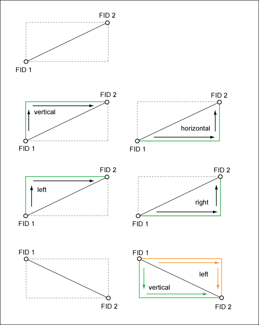
Applies to Orthogonal schema plans. Specifies the priority of the direction in which the schematic features are drawn.
|
|
Multiline Distribution |
Applies to orthogonal and geoschematic schema plans in the Electric CE module. |
|
Multiline Offset |
Applies to orthogonal and geoschematic schema plans in the Electric CE module. |
|
Sort Order |
Applies to orthogonal and geoschematic schema plans in the Electric CE module. |
Schematic features can be point or line features. They are stored in two feature classes.
- Point location feature class—Point feature class.
- Line location feature class—Line string feature class.
When you create the schema plan template, a new item is added under the Representation node. Click the schema plan to view the properties in the right pane.
Schema Plan Settings
Depending on the schema plan type, and depending on the module, in the Create Schematic dialog box, you specify additional settings. The Settings area only displays the settings that are valid for the selected schema plan type.
Direction Priority
For orthogonal schema plans, specifies the priority of the direction in which the schematic features are drawn.

The direction of the lines between two points is derived from the FID. For example, a line will be created from FID 1 to FID 2, either starting vertically, horizontally, drawing the line left to the real world feature, or drawing the line right to the real world feature.
Multiline Offset and Distribution (Electric CE)
In the Electric CE data model, you can specify the multiline offset and distribution, both for orthogonal and geoschematic plans.
- Multiline Offset— Specifies the offset distance between overlapping multiline conductor features and the parent single line feature. The offset line is drawn in parallel to the original feature. The offset is the distance between the parallel features. Unit is the industry model length unit.
- Multiline Distribution—Specifies the distribution of multiline conductor features around the parent line feature. Can be either
- Symmetric
- Left
- Right

The left or right distribution direction is defined by the FID.
Sort Order
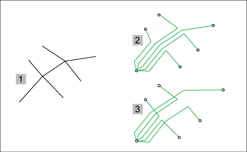
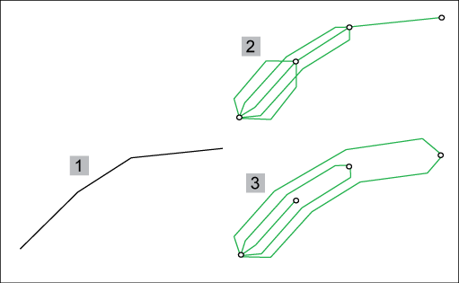
Specifies the order in which parallel conductors are drawn. Can either be Most Common Segments First or Least Common Segments First. For example, the conductors having the most segments in common should be drawn in the middle.

Use cases for Real World segments (1) represented in a schematic view.
- (2) uses the option Most Common Segments First.
- (3) uses the option Least Common Segments First.

For example, use the option Least Common Segments First (3), if the start and endpoints of the conductors are all on the main line.