Area topologies often represent parcels in cadastral applications. Parcels are defined by their borders and should incorporate data specific to the entire parcel. The border in this model corresponds to a set of lines and the area to a polygon. An area topology builds areas (polygons) from a set of lines.
An area topology consists of two feature classes, a centroid and a line feature class, and various properties.
An intersection can be performed with polygons as the primary feature class and polygons, line strings, and points as secondary feature classes. For intersections, you can use area topologies to build polygons from a set of lines for the primary feature class. See also Data Model: Intersections.
Arc Linearize Tolerance
When you create an area topology, you can set the default value for the arc linearize tolerance. You cannot change it later without dropping and recreating the topology.
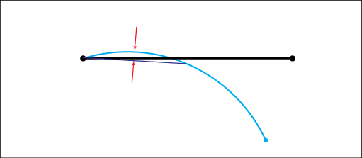
The arc linearize tolerance helps to overcome data impurity, especially minor overlapping of arc segments. If overlapping is detected, then the arc segment is linearized in the same way that the respective segments, at the beginning or the end of the arc, are replaced by linear segments. If such linearization overcomes the topology error and overlapping disappears, the polygon is stored. Otherwise a topology error is returned.

Area topology: By setting the arc linearization tolerance, you can control overlapping of arcs and lines.
The value for arc linearize tolerance cannot be smaller than the spatial tolerance for the line feature class. It should be 2 – 5 times the spatial tolerance of the line feature class.
Area Modification Outside Perimeter
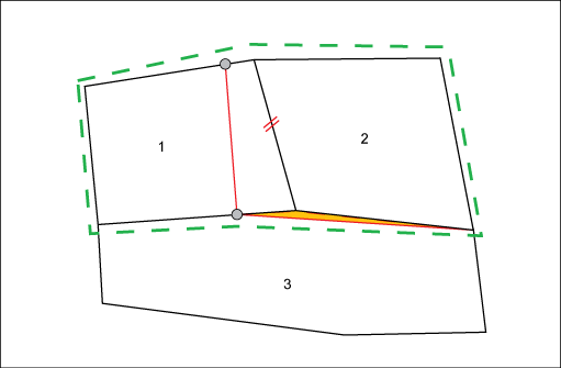
Modifying an edge inside an area feature perimeter affects the corresponding areas located to the left and right of it. If these areas lie outside the perimeter, or within the perimeter buffer, the modification can be cancelled if it is significant.

If the industry model is job enabled, and if the current job has a perimeter assigned, polygons outside the perimeter are checked, to see whether the area is changing more than the specified tolerance. For example, Swiss land management does not allow changes greater than 1m2.
To create an area topology
- In the Infrastructure Administrator, do one of the following:
- Click Enterprise and connect to the enterprise industry model . Open a project.
- Click File and open an industry model drawing or template.
- Click the Data Model node for the industry model.
- Right-click the Topologies node item and click .
- In the Area Topology dialog box, define the topology.
Define the properties and click OK.
Area Topology Dialog Box
Description
Topology area
Contains general settings for the topology.
Name
Specifies the name of the topology.
Centroid Feature Class
Selects a centroid feature class (FC). A centroid stores the essential information of a polygon. Multiple topologies can share a centroid.
Line Feature Class
Selects the edge FC. One edge FC can participate in several topologies.
Tolerance area
Arc Linearize
Sets the arc linearize value. The default value is 0.08.
Max. Area Modification Outside Perimeter
Sets the tolerance for area modifications of polygons that lie outside, or partially outside of the job perimeter.
Advanced area
Centroids Filter Expression
Selects the centroids to be used to build the area topology. Enter a a filter for the centroid feature class as follows:
<column> = <value>, for example: ID_TYPE=24.
Lines Filter Expression
Selects the edges to be used to build the area topology.