SplineShape : Shape
splineShape - superclass: Shape; super-superclass:Node - classID: #(10, 0)- Rendering Rollout
- Interpolation Rollout
- Selection Rollout
- Soft Selection Rollout
- Geometry Rollout
- Surface Properties Rollout
- Shape Methods
- Spline Methods
- Segment Methods
- Knot Methods
SplineShapes are the general editable versions of all the shape objects, in the same way that Editable Meshes relate to geometry objects. They are the objects that a shape is converted to when you apply an Edit Spline modifier and the result of collapsing a modifier stack on a shape base object. MAXScript lets you construct SplineShapes from scratch, add individual curves (splines) and controls points (knots), or modify an existing shape by converting it to a SplineShape using the methods listed below.
Constructors:
splineShape...
bezierShape...
convertToSplineShape <shape>
For practical examples of creating and modifying spline shapes, see also
MAXScript FAQ:How do I create a line between two points?
How To ... Flatten a SplineShape
How To ... Draw a Freehand Spline
You must convert existing shapes to SplineShapes (Editable Splines) to operate on them with the methods listed in this topic. Use the convertToSplineShape() function to do this.
Only the updateShape() function updates the shape's internal caches and images in 3ds Max viewports. This is because updates can be computationally expensive and you do not want them performed on every function call. However, you must make sure you do call the updateShape() function after a series of changes and before the shape is to be worked on in 3ds Max or by other functions in MAXScript.
The in and out vectors for Bezier control points are given as vector handle coordinates, not as true vectors as the names suggests.
Coordinates are given in the MAXScript working coordinate system. This is important to note if you are familiar with the corresponding SDK spline functions that always work in object-local coordinates.
If the updateShape() function is called on an object that is selected and currently open in the Modify panel, it will drop the current selection to avoid a potential crash in 3ds Max, which at the moment does not support scripted changes to an object open in the Modify panel.
If you are creating or modifying a spline object and have not yet run updateShape() on the spline, 3ds Max will crash if you minimize and then maximize the 3ds Max window. This is because the spline is only partially created and the internal 3ds Max spline structure is left in an unstable state.
Properties
Rendering Rollout
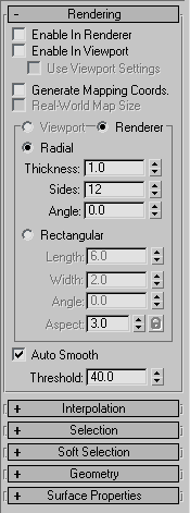
Properties:
<SplineShape>.render_renderable BooleanClass default: false -- boolean; renderableToggles the "Enable in Renderer" checkbox on and off.
Available in 3ds Max 8 and higher.
<SplineShape>.render_displayRenderMesh BooleanClass default: false -- boolean; displayRenderMeshToggles the "Enable In Viewport" checkbox on and off. When set to true, the mesh will be displayed in the viewports.
Available in 3ds Max 8 and higher.
<SplineShape>.render_useViewportSettings BooleanClass default: false -- boolean; useViewportSettingsToggles the "Use Viewport Settings" checkbox on and off.
When set to true, the mesh displayed in the viewport will use the Viewport settings.
When false, the Renderer settings will be used for the viewport mesh.
Available in 3ds Max 8 and higher.
<SplineShape>.render_mapcoords BooleanClass default: false -- boolean; mapcoordsToggles mapping coordinates generation on and off.
The U coordinate wraps once around the thickness of the spline; the V coordinate is mapped once along the length of the spline.
Available in 3ds Max 8 and higher.
<SplineShape>.realWorldMapSize BooleanClass default: false -- booleanToggles the real-world map size option on and off.
Available in 3ds Max 8 and higher.
<SplineShape>.render_displayRenderSettings BooleanClass default: true -- boolean; displayRenderSettingsToggles the state of the Viewport/Renderer radio buttons.
When set to true, the Renderer settings will be displayed in the rollout.
When false, the Viewport settings will be shown instead.
Available in 3ds Max 8 and higher.
<SplineShape>.render_rectangular BooleanClass default: false -- booleanWhen set to true, enables the Rectangular cross-section mode to be used in the renderer.
When false (default), enables the Radial cross-section mode.
Corresponds to the Radial/Rectangular radio buttons in the UI in the Renderer mode.
Available in 3ds Max 8 and higher.
<SplineShape>.render_viewport_rectangular BooleanClass default: false -- booleanWhen set to true, enables the Rectangular cross-section mode to be used in the viewports.
When false (default), enables the Radial cross-section mode.
Corresponds to the Radial/Rectangular radio buttons in the UI in the Viewport mode.
Available in 3ds Max 8 and higher.
Renderer - Radial Cross-Section
Properties:
<SplineShape>.render_thickness Float default: 1.0 -- animatable; thicknessGets/Sets the diameter of the Radial renderable spline mesh.
Available in 3ds Max 8 and higher.
<SplineShape>.render_sides Integer default: 12 -- animatable; sidesGets/Sets the number of sides for the spline mesh in the renderer.
For example, a value of four will give you a square cross section.
Available in 3ds Max 8 and higher.
<SplineShape>.render_angle Float default: 0.0 -- animatable; angleGets/Sets the rotational position of the Radial cross-section in the renderer.
Available in 3ds Max 8 and higher.
Renderer - Rectangular Cross-Section
Properties:
<SplineShape>.render_length Float default: 6.0 -- animatableGets/Sets the length of the Rectangular renderable spline mesh.
Available in 3ds Max 8 and higher.
<SplineShape>.render_width Float default: 2.0 -- animatableGets/Sets the width of the Rectangular renderable spline mesh.
Available in 3ds Max 8 and higher.
<SplineShape>.render_angle2 Float default: 0.0 -- animatableGets/Sets rotational position of the Radial cross-section in the renderer.
Available in 3ds Max 8 and higher.
<SplineShape>.render_aspect_locked BooleanClass default: false -- booleanControls the state of the Aspect Lock checkbutton.
When set to true, changing the Width will affect the Height and vice-versa, preserving the aspect at the time the lock was engaged.
Available in 3ds Max 8 and higher.
Viewport - Radial Cross-Section
Properties:
<SplineShape>.render_viewport_thickness Float default: 1.0 -- float; viewport_thicknessGets/Sets the diameter of the Radial renderable spline mesh in the viewport.
Available in 3ds Max 8 and higher.
<SplineShape>.render_viewport_sides Integer default: 12 -- integer; viewport_sidesGets/Sets the number of sides for the Radial spline mesh in the viewports.
For example, a value of four will give you a square cross section.
Available in 3ds Max 8 and higher.
<SplineShape>.render_viewport_angle Float default: 0.0 -- float; viewport_angleGets/Sets the rotational position of the cross-section in the viewports.
Available in 3ds Max 8 and higher.
Viewport - Rectangular Cross-Section
Properties:
<SplineShape>.render_viewport_length Float default: 6.0 -- floatGets/Sets the length of the Rectangular spline mesh in the viewports.
Available in 3ds Max 8 and higher.
<SplineShape>.render_viewport_width Float default: 2.0 -- floatGets/Sets the width of the Rectangular spline mesh in the viewports.
Available in 3ds Max 8 and higher.
<SplineShape>.render_viewport_angle2 Float default: 0.0 -- floatGets/Sets the rotational position of the Rectangular cross-section in the viewports.
Available in 3ds Max 8 and higher.
<SplineShape>.render_viewport_aspect_locked BooleanClass default: false -- booleanControls the state of the Aspect Lock checkbutton.
When set to true, changing the Width will affect the Height and vice-versa, preserving the aspect at the time the lock was engaged.
Available in 3ds Max 8 and higher.
Auto Smooth
Properties:
<SplineShape>.render_auto_smooth BooleanClass default: true -- booleanControls the state of the Auto Smooth checkbox.
When set to true, auto smoothing will be enabled.
Available in 3ds Max 8 and higher.
<SplineShape>.render_threshold Float default: 40.0 -- animatable;Gets/sets the Auto Smooth Threshold value. Available in 3ds Max 8 and higher.
Up to 3*N vertex and tangent coordinates are available as properties, where N is the number of vertices in the SplineShape.
A vertex and its tangents are available as properties once a controller is assigned to the vertex.
Controllers can be assigned to vertices using the animateVertex() method described in Scripting Vertex and Control Point Animation.
For example, if a circle object is collapsed to a SplineShape and some of its vertices are animated, the properties for the vertices and tangents will be similar to:
$Circle01.Spline_1___InVec_1 Point3 value: [-75,33,0] -- animatable
$Circle01.Spline_1___Vertex_1 Point3 value: [-75,33,0] -- animatable
$Circle01.Spline_1___OutVec_1 Point3 value: [-50,0,0] -- animatable
$Circle01.Spline_1___InVec_2 Point3 value: [-20,-33,0] -- animatable
$Circle01.Spline_1___Vertex_2 Point3 value: [7,-66,0] -- animatable
$Circle01.Spline_1___OutVec_2 Point3 value: [32,-95,0] -- animatable
Interpolation Rollout
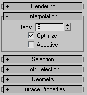
Properties:
<splineshape>.steps Integer default: 6 -- integerControls the Interpolation Steps in the Interpolation rollout.
<splineshape>.optimize Boolean default: true -- booleanControls the state of the Optimize checkbox in the Interpolation rollout.
<splineshape>.adaptive Boolean default: false -- booleanControls the state of the Adaptive checkbox in the Interpolation rollout.
Selection Rollout
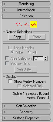
No Related Properties or Method exposed to MAXScript.
Soft Selection Rollout

No Related Properties or Method exposed to MAXScript.
Geometry Rollout

Create, Break, Attach
Methods:
splineOps.startCreateLine <editable_spline_or_line_node_or_modifier>Enters the "Create Line" command mode. It is valid in all Sub-Object levels and when not in the Sub-Object mode.
See Editable Spline Modify Panel Command Modes and Operations for the full list of UI-related methods.
splineOps.startBreak <editable_spline_or_line_node_or_modifier>Enters the "Break" command mode. It is valid in Vertex and Segment Sub-Object levels.
See Editable Spline Modify Panel Command Modes and Operations for the full list of UI-related methods.
splineOps.startAttach <editable_spline_or_line_node_or_modifier>Enters the "Attach" command mode. It is valid in all Sub-Object levels and when not in the Sub-Object mode.
See Editable Spline Modify Panel Command Modes and Operations for the full list of UI-related methods.
splineOps.attachMultiple <editable_spline_or_line_node_or_modifier>Displays the Attach Multiple dialog allowing the user to select multiple shapes to attach. Valid in all Sub-Object levels and when not in the Sub-Object mode.
See Editable Spline Modify Panel Command Modes and Operations for the full list of UI-related methods.
Refine
Methods:
splineOps.startRefine <editable_spline_or_line_node_or_modifier>Enters the "Refine" command mode. It is valid in Vertex and Segment Sub-Object levels. This method does not turn off the Connect checkbox, so it is effectively the same as the startRefineConnect() method.
See Editable Spline Modify Panel Command Modes and Operations for the full list of UI-related methods.
splineOps.startRefineConnect <editable_spline_or_line_node_or_modifier>Enters the "Refine" command mode. It is valid in Vertex and Segment Sub-Object levels. This method does not turn on the Connect checkbox, so it is effectively the same as the startRefine() method.
See Editable Spline Modify Panel Command Modes and Operations for the full list of UI-related methods.
Weld, Connect, Insert, Make First, Fuse, Reverse, Cycle
Methods:
splineOps.weld <editable_spline_or_line_node_or_modifier>Welds the selected vertices. It is valid in the Vertex Sub-Object level.
See also the related methods in ShapeMethods-Weld.
See Editable Spline Modify Panel Command Modes and Operations for the full list of UI-related methods.
splineOps.startConnect <editable_spline_or_line_node_or_modifier>Enters the "Connect" command mode. It is valid in the Vertex Sub-Object level.
See Editable Spline Modify Panel Command Modes and Operations for the full list of UI-related methods.
splineOps.startInsert <editable_spline_or_line_node_or_modifier>Enters the "Insert" command mode. It is valid in all Sub-Object levels, and when not in the Sub-Object mode.
See Editable Spline Modify Panel Command Modes and Operations for the full list of UI-related methods.
splineOps.makeFirst <editable_spline_or_line_node_or_modifier>Makes the selected vertices the first vertex in the spline. It is valid in the Vertex Sub-Object level.
See Editable Spline Modify Panel Command Modes and Operations for the full list of UI-related methods.
splineOps.fuse <editable_spline_or_line_node_or_modifier>Fuses the selected vertices. Valid in the Vertex Sub-Object level.
See Editable Spline Modify Panel Command Modes and Operations for the full list of UI-related methods.
splineOps.reverse <editable_spline_or_line_node_or_modifier>Reverses the order of vertices in the selected splines. It is valid in the Spline Sub-Object level.
See Editable Spline Modify Panel Command Modes and Operations for the full list of UI-related methods.
splineOps.cycle <editable_spline_or_line_node_or_modifier>Cycles through the vertices of the spline, selecting each vertex.
At least one vertex must be selected before calling this method, or no vertex is selected.
If more than one vertex is selected when this method is called, the first vertex of the first shape is selected.
Valid in the Vertex Sub-Object level.
See Editable Spline Modify Panel Command Modes and Operations for the full list of UI-related methods.
CrossInsert, Fillet, Chamfer, Outline
Methods:
splineOps.startCrossInsert <editable_spline_or_line_node_or_modifier>Enters the "CrossInsert" command mode. It is valid in the Vertex Sub-Object level.
See Editable Spline Modify Panel Command Modes and Operations for the full list of UI-related methods.
splineOps.startFillet <editable_spline_or_line_node_or_modifier>Enters the "Fillet" command mode. It is valid in the Vertex Sub-Object level.
See Editable Spline Modify Panel Command Modes and Operations for the full list of UI-related methods.
splineOps.startChamfer <editable_spline_or_line_node_or_modifier>Enters the "Chamfer" command mode. It is valid in the Vertex Sub-Object level.
See Editable Spline Modify Panel Command Modes and Operations for the full list of UI-related methods.
splineOps.startOutline <editable_spline_or_line_node_or_modifier>Enters the "Outline" command mode. It is valid in the Spline Sub-Object level.
See Editable Spline Modify Panel Command Modes and Operations for the full list of UI-related methods.
Boolean
Methods:
splineOps.startUnion <editable_spline_or_line_node_or_modifier>Enters the "Boolean Union" command mode. It is valid in the Spline Sub-Object level.
Only one closed spline must be selected to enter this command mode.
See Editable Spline Modify Panel Command Modes and Operations for the full list of UI-related methods.
splineOps.startSubtract <editable_spline_or_line_node_or_modifier>Enters the "Boolean Subtract" command mode. It is valid in the Spline Sub-Object level.
Only one closed spline must be selected to enter this command mode.
See Editable Spline Modify Panel Command Modes and Operations for the full list of UI-related methods.
splineOps.intersect <editable_spline_or_line_node_or_modifier>Enters the "Boolean Intersect" command mode. It is valid in the Spline Sub-Object level.
Only one closed spline must be selected to enter this command mode.
See Editable Spline Modify Panel Command Modes and Operations for the full list of UI-related methods.
Mirror
Methods:
splineOps.mirrorHoriz <editable_spline_or_line_node_or_modifier>Mirrors the selected splines horizontally. It is valid in the Spline Sub-Object level.
See Editable Spline Modify Panel Command Modes and Operations for the full list of UI-related methods.
splineOps.mirrorVert <editable_spline_or_line_node_or_modifier>Mirrors the selected splines vertically. It is valid in the Spline Sub-Object level.
See Editable Spline Modify Panel Command Modes and Operations for the full list of UI-related methods.
splineOps.mirrorBoth <editable_spline_or_line_node_or_modifier>Mirrors the selected splines horizontally and vertically. It is valid in the Spline Sub-Object level.
See Editable Spline Modify Panel Command Modes and Operations for the full list of UI-related methods.
Trip, Extend
Methods:
splineOps.startTrim <editable_spline_or_line_node_or_modifier>Enters the "Trim" command mode. It is valid in the Spline Sub-Object level.
See Editable Spline Modify Panel Command Modes and Operations for the full list of UI-related methods.
splineOps.startExtend <editable_spline_or_line_node_or_modifier>Enters the "Extend" command mode. It is valid in the Spline Sub-Object level.
See Editable Spline Modify Panel Command Modes and Operations for the full list of UI-related methods.
Copy, Paste Tangent
Methods:
splineOps.startCopyTangent <editable_spline_or_line_node_or_modifier>Enters the "Copy Tangent" command mode. It is valid in the Vertex Sub-Object level.
See Editable Spline Modify Panel Command Modes and Operations for the full list of UI-related methods.
splineOps.startPasteTangent <editable_spline_or_line_node_or_modifier>Enters the "Paste Tangent" command mode. It is valid in the Vertex Sub-Object level.
See Editable Spline Modify Panel Command Modes and Operations for the full list of UI-related methods.
Hide, Unhide
Methods:
splineOps.hide <editable_spline_or_line_node_or_modifier>Hides the selected sub-objects. It is valid in all Sub-Object levels.
See Editable Spline Modify Panel Command Modes and Operations for the full list of UI-related methods.
splineOps.unhideAll <editable_spline_or_line_node_or_modifier>Unhides all hidden sub-objects. It is valid in all Sub-Object levels and when not in the Sub-Object mode.
See also the related methods in Shape Methods -Hide,Unhide.
See Editable Spline Modify Panel Command Modes and Operations for the full list of UI-related methods.
Bind, Unbind
splineOps.startBind <editable_spline_or_line_node_or_modifier>Enters the "Bind" command mode. It is valid in the Vertex Sub-Object level.
See Editable Spline Modify Panel Command Modes and Operations for the full list of UI-related methods.
splineOps.unbind <editable_spline_or_line_node_or_modifier>Unbinds the selected vertices. It is valid in the Vertex Sub-Object level.
See also related methods in ShapeMethods-Bind,Unbind.
See Editable Spline Modify Panel Command Modes and Operations for the full list of UI-related methods.
Delete, Close
splineOps.delete <editable_spline_or_line_node_or_modifier>Deletes the selected sub-objects. It is valid in all Sub-Object levels.
See Editable Spline Modify Panel Command Modes and Operations for the full list of UI-related methods.
splineOps.close <editable_spline_or_line_node_or_modifier>Closes the selected splines. It is valid in the Spline Sub-Object level.
See Editable Spline Modify Panel Command Modes and Operations for the full list of UI-related methods.
Divide, Detach, Explode
splineOps.divide <editable_spline_or_line_node_or_modifier>Divides the selected segments. It is valid in the Segment Sub-Object level.
See Editable Spline Modify Panel Command Modes and Operations for the full list of UI-related methods.
splineOps.detach <editable_spline_or_line_node_or_modifier>Displays the Detach dialog allowing the user to specify an object name. It is valid in all Sub-Object levels.
See Editable Spline Modify Panel Command Modes and Operations for the full list of UI-related methods.
splineOps.explode <editable_spline_or_line_node_or_modifier>Explodes each segment in the selected splines into separate splines or objects. It is valid in the Spline Sub-Object level.
See Editable Spline Modify Panel Command Modes and Operations for the full list of UI-related methods.
Surface Properties Rollout

Methods:
splineOps.selectByID <editable_spline_or_line_node_or_modifier>Presses the Select ID button.
See also the related methods in ShapeMethods-MaterialID.
See Editable Spline Modify Panel Command Modes and Operations for the full list of UI-related methods.
Methods
Shape Methods
updateShape <shape>Updates the shape's internal caches and viewport display to account for all the changes made by other functions in this kit. This update must be done before 3ds Max or any other code tries to work with a modified shape object.
The updateShape() function makes any scripted changes to a base object spline shape propagate into the bottom of any modifier stack that is present.
Note that there is no check to warn you that modifications such as, topology changes might invalidate modifiers already in the stack.
This is equivalent to opening and modifying the base object in a Modify panel ignoring its warnings about invalidating the object.
resetShape <shape>Clears all the spline curves out of a shape.
numSplines <shape>Returns the number of spline curves in the shape as an integer.
Equivalent to <shape>.numSplines .
setFirstSpline <shape> <spline_index_integer>Rolls the order of the splines in a shape around so that the numbered spline is the first spline in the shape.
This is useful when working with multi-spline shapes in the Lofter and some other modifiers such as, Surface Tools which are sensitive to spline order.
Weld
addAndWeld <to_shape> <from_shape> <weldthreshold_float>Add the splines from one spline shape to the specified bezier shape.
The weld threshold will weld the endpoints of the new splines onto endpoints of existing ones if they are within the specified distance.
Bind and Unbind
bindKnot <shape> <isEnd_boolean> <splineId_integer> <segIndex_integer> <splineSegId_integer>Binds the first or end knot of a spline to the midpoint of the specified segment.
A bind acts as a constraint, it constrains the first point or the end point of a spline to the mid point of a segment.
If <isEnd_boolean> is true , the end knot of the spline is bound, otherwise the first knot is bound.
<splineId_integer> specifies the index of the spline the first/end knot to bind belongs to, <segIndex_integer> specifies the index of the segment to bind to, and <splineSegId_integer> specifies the index of the spline the bind to segment belongs to.
unBindKnot <shape> <spline_index_integer> <isEnd_boolean>Unbinds the specified end/first knot of the given spline.
updateBindList <shape>Called when the topology changes to update the bind list. For example, when knots are deleted from the bound spline or the spline bound to.
Hide and Unhide
hideselectedsplines <shape>Hides the selected splines in the shape.
hideselectedsegments <shape>Hides the selected segments in the shape.
hideselectedverts <shape>Hides the segments attached to the selected knots in the shape.
unhidesegments <shape>Unhides all segments in the shape.
Material ID
materialID <shape> <spline_index_integer> <segment_index_integer>Returns the material id for the given segment of the given shape object.
Vertex Animation
animateVertex <shape> <vertex_spec>Applies controllers to the specified vertices and tangents of the splineshape, where <vertex_spec> is one of these:
<integer_index>
<integer_index_array>
#all
By assigning controllers to the vertices and tangents, the vertices and tangents are added to the Driver subAnim and appear as animatables in the Track View, allowing further scripting of the vertices and tangents.
FOR EXAMPLE
animateVertex $Circle01 #all
The vertices to be animated are specified by index number or with the keyword #all to animate all vertices.
See also Class and Object Inspector Functions and Scripting Vertex and Control Point Animation for details on accessing the splineshape vertices and tangents. The controller values assigned to the vertices and tangent handles is in object space. See Using Node Transform Properties for information on converting between world space to object space.
For examples of creating and modifying spline shapes, see also
MAXScript FAQ: How do I create a line between two points?
How To ... Flatten a SplineShape
How To ... Draw a Freehand Spline
Spline Methods
addNewSpline <shape>Adds a new spline curve to the spline shape and returns an integer reflecting the spline index of the newly added spline curve.
Individual spline curves are given index numbers starting at one.
The addNewSpline() function adds new spline curves to the end of the list of curves in a shape.
getSplineSelection <shape>Returns the indices of the selected splines in the shape as an array of integers.
setSplineSelection <shape> <spline_index_array> [keep:<boolean> ]Selects the splines specified by <spline_index_array> in the specified shape.
<spline_index_array> is an array of integers specifying the spline indices.
Splines already selected are de-selected unless keep:true is specified.
deleteSpline <shape> <spline_index_integer>Deletes the indexed spline curve from the shape.
The remaining curves are renumbered to account for the deletion.
numSegments <shape> <spline_index_integer>Returns the number of line segments in the indexed spline as an integer.
This is the same as the number of knots for closed splines and one less for open splines.
numKnots <shape> [ <spline_index_integer> ]Returns the number of knots (also known as vertices or control points) in the indexed spline as an integer.
If the spline index is not specified, returns the number of knots in the entire shape.
isClosed <shape> <spline_index_integer>Returns true if the indexed spline is closed, false if it is open.
close <shape> <spline_index_integer>Closes the indexed spline.
open <shape> <spline_index_integer>Opens the indexed spline between its last and first knots.
reverse <shape> <spline_index_integer> [keepFirstKnot:true|false]Reverses the order of the knots in the indexed spline.
The optional keepFirstKnot keyword parameter indicates whether to keep the first knot in place. If false (the default if not specified), the first knot becomes the last, and the last the first. This differs from the behavior of the Reverse button in the Spline UI.
setFirstKnot <shape> <spline_index_integer> <knot_index_integer>Rolls the order of the knots in the indexed spline around so that the specified knot becomes the first knot in the spline.
weldSpline <splineShape node> <tolerance>Welds the selected knots in the specified splineShape that are within the specified tolerance.
Available in 3ds Max 2008 and higher.
Previously, available in the Avguard Extensions .
EXAMPLE:
(
local sp = splineShape()
addnewSpline sp
addKnot sp 1 #corner #line [20,10,0]
addKnot sp 1 #corner #line [-20,11,0]
addKnot sp 1 #corner #line [-20,-11,0]
addKnot sp 1 #corner #line [20,-10,0]
close sp 1
updateShape sp
select sp
subobjectlevel = 1
setKnotSelection sp 1 #(1,4) keep:false -- Select the right most knots
weldSpline sp 21.0
local knotCount = numknots sp
if (knotCount != 3) do
 throw ("Spline should have 3 knots, found "+ (knotCount as string))
)
getSegLengths <splineShape> <spline_index> [cum:<boolean>] \
[byVertex:<boolean>] [numArcSteps:<integer>]
Returns an array of segment lengths or vertex distances by spline fraction and length, and total spline length.
Double precision calculations are very accurate.
If cum:true, the results are cumulative, otherwise they are relative.
If byVertex:true, the results are per vertex, otherwise per segment.
Defaults: cum:false byVertex:false numArcSteps:100
subdivideSegment <splineShape> <spline_index> <seg_index> <divisions>Divides the segment into the specified number of divisions.
Double precision calculations are very accurate.
interpCurve3D <splineShape> <spline_index> <param_float> [pathParam:<boolean>]Returns a <point3> coordinate on the indexed curve.
If pathParam:false, param_float is the fraction of the spline length, otherwise it is a segment-based (path) fraction.
Default is pathParam:false.
tangentCurve3D <splineShape> <spline_index> <param_float> [pathParam:<boolean>]Returns a <point3> tangent on the indexed curve.
If pathParam:false, param_float is the fraction of the spline length, otherwise it is a segment-based (path) fraction.
Default is pathParam:false.
findPathSegAndParam <shape> <curve_num> <param>Returns a point2 value containing the segment and segment fraction for the specified vertex-interpolated spline parameter.
The first and second arguments specify the shape and the spline within the shape to interpolate, the third argument is the parameter to interpolate.
For example, passing a parameter of 0.5 with a 10 segments spline will always return a point2 value containing either [6,0.0] (or very close to 0) or [5,1.0] because the middle of a 10 segments spline using vertex interpolation is always the vertex between the 5 th and the 6 th segment.
See the notes below for information about interpolation methods.
Available in 3ds Max 2008 and higher. Previously, available in the Avguard Extensions.
findLengthSegAndParam <shape> <curve_num> <param>Returns a point2 value containing the segment and segment fraction for the specified length-interpolated spline parameter.
The first and second arguments specify the shape and the spline within the shape to interpolate, and the third argument is the parameter to interpolate.
In contrast to findPathSegAndParam() , this method takes the actual length of the segments into account, normalizing the complete length between 0.0 and 1.0 and then interpolating along the length, so a parameter of 0.5 with a 10 segments spline will always return the segment and parameter within the segment that lies in the exact middle of the spline's length, varying based on the actual segment lengths/vertex distribution within the spline.
See the notes below.
Available in 3ds Max 2008 and higher. Previously, available in the Avguard Extensions.
VERTEX AND LENGTH INTERPOLATION METHODS:
There are two methods to interpolate a position along the spline: vertex interpolation and length interpolation.
When using vertex interpolation (path interpolation), the spline is seen as a number of segments where each segment between two vertices is a normalized space from 0.0 to 1.0. The distance between the two vertices of a segment is ignored during the interpolation, which means that if the lengths of the segments are different, interpolating linearly along the spline will result in varying speed.
You can visualize this on a Path Constraint with Constant Velocity unchecked where the object is moving faster between two vertices when the segment between them is longer (see the image below).
When using length interpolation, the whole spline length is normalized, so a parameter of 0.5 will be exactly in the middle of the spline regardless of the segments' lengths. The speed of a point interpolated along the spline using a parameter that changes linearly between 0.0 and 1.0 will remain constant along the whole spline even if the vertex placement is irregular.
This can be demonstrated when checking the Constant Velocity checkbox in the Path Constraint that enables the length interpolation:

In this image, the top object is a SplineShape with varying segment length and ten segments.
The middle object is a copy of the same shape used as a path by a Point Helper. The Constant Velocity checkbox was unchecked in the Path Constraint causing it to use vertex interpolation. For 100 frames, it divided the shape in ten segments and placed ten samples on each segment resulting in varying speed dependent on the length of the segment.
The bottom object is a copy of the same shape used as a path by another Point Helper, but this time Constant Velocity is turned on causing it to use length interpolation. You can see clearly that the samples are evenly spaces along the full length of the shape disregarding the distances between the vertices defining the segments.
The time slider was set of frame 50. The length interpolation at the bottom places the point helper exactly at the middle of the path shape, while the vertex interpolation places it exactly on the vertex between the 5 th and the 6 th segment.
EXAMPLE:
( local sp = splineShape()
addnewSpline sp
for i = 0 to 10 do
(
addknot sp 1 #smooth #curve [i*10, i*i, i*10]
)
updateShape sp
for i = 0.0 to 1.0 by 0.05 do
(
local pt1= findPathSegAndParam sp 1 i
local pt2= findLengthSegAndParam sp 1 i
format "% : % \t %\n"i pt2 pt1
)
)
OUTPUT:
0.0 : [1,0] [1,0]
0.05 : [1,0.633532] [1,0.5]
0.1 : [2,0.261918] [1,1]
0.15 : [2,0.883245] [2,0.5]
0.2 : [3,0.486351] [2,1]
0.25 : [4,0.0810387] [3,0.5]
0.3 : [4,0.650404] [3,1]
0.35 : [5,0.206902] [4,0.5]
0.4 : [5,0.74293] [5,2.98023e-007]
0.45 : [6,0.261026] [5,0.5]
0.5 : [6,0.762596] [6,5.96046e-007]
0.55 : [7,0.246405] [6,0.500001]
0.6 : [7,0.714253] [7,5.96046e-007]
0.65 : [8,0.16969] [7,0.500001]
0.7 : [8,0.605653] [8,5.96046e-007]
0.75 : [9,0.0387986] [8,0.500001]
0.8 : [9,0.445251] [9,5.96046e-007]
0.85 : [9,0.851703] [9,0.500001]
0.9 : [10,0.241028] [10,5.96046e-007]
0.95 : [10,0.620515] [10,0.500001]
1.0 : [10,1] [10,0.999999]
OK
The vertex interpolation at the right side hits more or less precisely the start or end vertex and the center of each of the 10 segments because we are stepping with 1/20 th per iteration, while the length interpolation takes into account the actual length of all segments and moves smoothly along the spline.
interpBezier3D <splineShape> <spline_index> <segment_index> <param_float> pathParam:<boolean>Returns a point3 coordinate for the segment and segment fraction on the indexed curve.
If pathParam:false, param_float is the fraction of the segment length, otherwise it is a segment-based (path) fraction.
Default is pathParam:false .
Available in 3ds Max 2008 and higher.
Previously, available in the Avguard Extensions.
tangentBezier3D <splineShape> <spline_index> <segment_index> <param_float> pathParam:<boolean>Returns a point3 tangent for the segment and segment fraction on the indexed curve.
If pathParam:false, param_float is the fraction of the segment length, otherwise it is a segment-based (path) fraction.
Default is pathParam:false.
Available in 3ds Max 2008 and higher.
Previously, available in the Avguard Extensions.
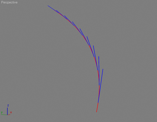
EXAMPLE:
(
local sp = splineShape()
addnewSpline sp
for i = 1 to 100 by 10 do
(
addknot sp 1 #smooth #curve [i, (i*i / 100.0), i]
)
updateShape sp
sp.wirecolor = color 255 0 0
local count = numknots sp - 1
for i = 1 to count do
(
local pathp = true
local pt = interpBezier3D sp 1 i 0.50 pathParam:pathp
local tn = tangentBezier3D sp 1 i 0.50 pathParam:pathp
local sr = splineShape()
addnewSpline sr
addknot sr 1 #corner #line pt
addknot sr 1 #corner #line (pt + (tn * 30))
updateShape sr
sr.wirecolor =blue
)
)
RESULT:
For examples of creating and modifying spline shapes, see also
MAXScript FAQ:How do I create a line between two points?
How To ... Flatten a SplineShape
How To ... Draw a Freehand Spline
Segment Methods
getSegmentType <shape> <spline_index_integer> <seg_index_integer>Gets the segment type of the indexed segment in the indexed spline.
setSegmentType <shape> <spline_index_integer> <seg_index_integer> (#curve | #line)Sets the segment type of the indexed segment in the indexed spline.
refineSegment <shape> <spline_index_integer> <seg_index_integer> <seg_interp_param_float>Adds a new knot to the indexed segment of the indexed curve at a place along the indexed segment corresponding to the given segment interpolation parameter.
This value is a float in the range of 0.0 to 1.0 specifying a proportion along the segment.
The new knot coordinates, and in-vector and out-vector are automatically computed to maintain the segment's existing curvature.
This is the primitive used by the refine() function in the Edit Spline modifier.
You can use the MAXScript spline path interpolation functions to derive segment parameters given that a curve's path interpolation parameter is divided evenly among the segments in a curve.
Given a path interpolation parameter u in a spline of m segments, the target segment is:
n = (m*u) as integer + 1The segment parameter is:
f = (u-(n-1)/m)*mThis can be refactored to the following which will reduce roundoff error in the calculation:
f = u*m-n+1The refineSegment() function returns the index of the newly inserted knot.
EXAMPLE:
s = splineShape() --create a spline shape
addNewSpline s --add a spline to it
addKnot s 1 #corner #line [0,0,0] --add a knot at origin
addKnot s 1 #smooth #curve [100,0,0] --add a knot @100 units along X
addKnot s 1 #corner #line [200,100,0] --add a third knot
updateShape s --update the shape
s.vertexTicks = true --enable vertex ticks
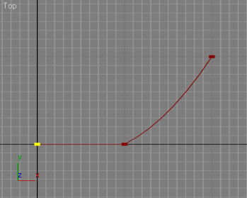
--We have two segments and three knots now.
refineSegment s 1 1 0.3 --divide the first segment at 30/70% ratio
updateShape s --update the shape to see the result
--Since our first segment was 100 units long, the vertex is exactly
--at 30 units from the origin, just as expected:
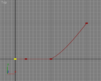
--now we have 3 segments - the original second segment is not third
refineSegment s 1 3 0.5 -- let's divide it in two equal parts
updateShape s --update the shape to see the result
--Because the segment is curved, the knot is not at equal distances
--to the two other knots along a straight line, but the
--distances ALONG THE CURVED SEGMENT are equal:
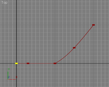
refineSegment s 1 4 0.8 --divide the new last segment at 80/20% ratio
updateShape s --and update the shape to see the result:

getSegSelection <shape> <spline_index_integer>Returns the indices of the selected segments in the specified shape spline as an array of integers.
setSegSelection <shape> <spline_index_integer> \
<segment_index_array> \
[keep: <boolean> ]
Selects the segments specified by <segment_index_array> in the specified shape spline.
<segment_index_array> is an array of integers specifying the segment indices.
Segments already selected are de-selected unless keep:true` is specified.
setMaterialID <splineShape> <spline_index> <seg_index> <matID>Sets the material ID of the specified spline segment.
getMaterialID <splineShape> <spline_index> <seg_index>Gets the material ID of the specified spline segment.
For examples of creating and modifying spline shapes, see also:
MAXScript FAQ:How do I create a line between two points?
How To ... Flatten a SplineShape
How To ... Draw a Freehand Spline
Knot Methods
addKnot <shape> <spline_index_integer> \
(#smooth | #corner | #bezier | #bezierCorner) \
(#curve | #line) <position_point3> \
[invec_point3 outvec_point3] \
[where_integer]
Adds a new knot (control point) to the indexed spline and returns an integer reflecting the index of the newly added knot.
The 3 rd argument specifies the type of the knot, the 4 th specifies the type of the segment leaving the knot.
The 5 th specifies the coordinates for the new point (given in the current working coordinate system).
If the knot type is #bezier or #bezierCorner , you must give the in-vector and out-vector handle coordinates as the 6 th and 7 th arguments. In the same way as splines are indexed in a shape, knots are indexed in a spline.
The optional last argument lets you specify where in the knot order the new knot is to be inserted, defaulting to the end of the spline if you leave this argument off.
deleteKnot <shape> <spline_index_integer> <knot_index_integer>Deletes the indexed knot in the indexed spline.
The remaining knots are renumbered to account for the deletion.
getKnotType <shape> <spline_index_integer> <knot_index_integer>Returns the knot type of the indexed knot in the indexed spline.
The value is one of the names #smooth , #corner , #bezier , or #bezierCorner .
setKnotType <shape> <spline_index_integer> <knot_index_integer> (#smooth | #corner | #bezier | #bezierCorner)Sets the knot type of the indexed knot in the indexed spline.
This is equivalent to the right-mouse-button change you can make to spline control-points using the Edit Spline modifier in 3ds Max.
getKnotPoint <shape> <spline_index_integer> <knot_index_integer>Retrieves the coordinates of the indexed knot as a point3 in the current working coordinate system.
setKnotPoint <shape> <spline_index_integer> <knot_index_integer> <point3>Sets the coordinates of the indexed knot in the indexed spline.
Coordinates are given in the current working coordinate system.
getInVec <shape> <spline_index_integer> <knot_index_integer>Retrieves the coordinates of the in-vector handle for the indexed knot as a point3 in the current working coordinate system.
setInVec <shape> <spline_index_integer> <knot_index_integer> <point3>Sets the coordinates of the in-vector handle of the indexed knot.
Coordinates are given in the current working coordinate system.
getOutVec <shape> <spline_index_integer> <knot_index_integer>Retrieves the coordinates of the out-vector handle for the indexed knot as a point3 in the current working coordinate system.
setOutVec <shape> <spline_index_integer> <knot_index_integer> <point3>Sets the coordinates of the out-vector handle of the indexed knot.
Coordinates are given in the current working coordinate system.
getKnotSelection <shape> <spline_index_integer>Returns the indices of the selected knots in the specified shape spline as an array of integers.
setKnotSelection <shape> <spline_index_integer> <knot_index_array> [keep: <boolean> ]Selects the knots specified by <knot_index_array> in the specified shape spline. <knot_index_array> is an array of integers specifying the knot indices.
Knots already selected are de-selected unless keep:true is specified.
For examples of creating and modifying spline shapes, see also:
MAXScript FAQ:How do I create a line between two points?