How To ... Develop a Vertex Renderer
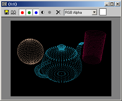
The tutorial will demonstrate the basics of rendering - transforming objects from 3D space into 2D images.To make it simple and fast (realtime!), the script will draw only vertices. The image will be redrawn every time the viewport is updated - changing the view, panning, zooming and orbiting will be reflected by the vertex renderer instantly!
Related topics:
Accessing Active Viewport Info, Type, and Transforms
NATURAL LANGUAGE
Create a macroScript.
Define a flag variable to remember whether the renderer is enabled or disabled
Define local variables to hold the render size and the front and back buffer images
Define a function to be called when the viewport redraws.
In the function,
Copy the back buffer into the front buffer
Go through all geometry objects and get their mesh
Get every vertex of the mesh, transform into image coordinates using the current view transformation matrix
Draw a pixel for the vertex in the front buffer
When done, display the image
Return the flag from the on isChecked handler.
When executed,
Invert the flag
Redefine the render size variables and the bitmaps
Register the viewport redraw callback function if the flag is true, unregister if false.
SCRIPT:
macroScript VertexRender category:"HowTo"
(
local VertexRendererEnabled = false
local screen_width, screen_height, back_vfb, front_vfb
fn VertexRendererFunction =
(
st = timestamp()
copy back_vfb front_vfb
for o in geometry where classof o != TargetObject do
(
theMesh = snapshotAsMesh o
dot_color = #(o.wirecolor)
theVertCount = theMesh.numverts
for v = 1 to theVertCount do
(
thePos = (getVert theMesh v)* viewport.getTM()
screen_origin = mapScreenToView [0,0] (thePos.z) [screen_width,screen_height]
end_screen = mapScreenToView [screen_width,screen_height] (thePos.z) [screen_width,screen_height]
world_size = screen_origin-end_screen
x_aspect = screen_width/(abs world_size.x)
y_aspect = screen_height/(abs world_size.y)
screen_coords = point2 (x_aspect*(thePos.x-screen_origin.x)) (-(y_aspect*(thePos.y-screen_origin.y)))
setPixels front_vfb screen_coords dot_color
)--end v loop
)--end o loop
display front_vfb
et = timestamp()
pushPrompt ("VertRender "+(1000.0/(et-st)) as string +" fps")
)--end fn

on isChecked return VertexRendererEnabled

on execute do
(
VertexRendererEnabled =not VertexRendererEnabled

if VertexRendererEnabled then
(
screen_width=RenderWidth
screen_height=RenderHeight
back_vfb = bitmap screen_width screen_height
front_vfb = bitmap screen_width screen_height
registerRedrawViewsCallback VertexRendererFunction
RedrawViews()
)
else
(
unRegisterRedrawViewsCallback VertexRendererFunction
close front_vfb
)
)--end on execute
)--end script

Step-By-Step
macroScript VertexRender category:"HowTo"
(
We start by defining a MacroScript with the name VertexRender which will appear in the category "HowTo". This will be an advanced macroScripts which will have on execute do or on is Checked do event handlers.
localVertexRendererEnabled= falseWe define a local variable to hold a flag determining whether the renderer is active or not. In the beginning, the variable will be set to false.
local screen_width,screen_height, back_vfb,front_vfbWe define a couple more local variables to hold the width and height of the image and the two bitmaps - the back buffer and the front buffer (see below for more info).
fn VertexRendererFunction =
(
This is the function that will be executed when the renderer is enabled and the viewport is being updated.
st = timestamp()To be able to output info on the rendering speed, we will use the timestamp function to get the current system time.
copy back_vfb front_vfbThen we will copy the back buffer into the front buffer, basically clearing the previous image. The back buffer could be changed to hold a background image, and the function would draw on top of it... For now, the back buffer image is set to black.
for o in geometry where classof o != TargetObject do
(
We loop through all scene geometry objects that are not target objects of lights, cameras etc. Note that we are not checking for hidden objects - you could add this to the code as an exercise! Right now, all objects will be drawn, even the hidden ones!
theMesh = snapshotAsMesh oThen we snapshot the objects as mesh into memory. This includes all modifiers AND space warps applied to the object.
dot_color = #(o.wirecolor)We define an array to be used for painting the vertices and use the wireframe color to draw.
theVertCount = theMesh.numvertsTo speed things up, we read the number of vertices in the mesh once. We will use this value below to limit the vertex loop:
for v = 1 to theVertCount do
(
The v variable will count from 1 to the number of vertices.
thePos = (getVert theMesh v)* viewport.getTM()The position of the v-th vertex has to be multiplied by the transformation matrix of the viewport. (If the viewport is a Camera, the viewport.getTM() returns the inverse of the camera's transformation matrix. If the viewport is a Perspective or Ortho view, the matrix is already inverted). By multiplying the vertex position by this matrix, we transform the 3D space coordinates into camera space!
screen_origin = mapScreenToView [0,0] (thePos.z) [screen_width,screen_height]Now we need to know the size of the projection plane with pixel size equal to the rendering image when placed at the depth of the current vertex. To calculate this, we will need the two extremes (upper left and lower right) points of the plane as 3D points in camera space.
Since thePos is already in camera coordinates, the.Z coordinate is the Z-depth of the point!The return value of mapScreenToView is a 3D point in camera space corresponding to the upper left corner of the projection plane.
end_screen = mapScreenToView [screen_width,screen_height] (thePos.z) [screen_width,screen_height]We do the same for the lower right corner of the projection plane.
Here is what we just did and why:
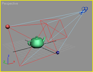
As you know, the camera has a cone (frustrum) with the top at the position of the camera. If the projection plane would "travel" along the Z axis of the camera, the farther it gets from the "eye", the larger it becomes in world units, but the number of pixels in the final image remains the same.

On the screenshot, you can see a camera and two projection planes (shown as red X). You can also see that the size of the projection plane is increasing as it gets farther from the camera.
The farther projection plane is exactly at the depth of the teapot's position in camera space.
The red sphere in the upper left corner of the projection plane corresponds to the screen_origin coordinate calculated above. To create the image, the screen_origin value was calculated, then the MAXScript line of code
sphere pos:(screen_origin*$Camera01.transform)was called to create a sphere in world coordinates representing that point. ( screen_origin was originally in camera space, multiplying it by the camera's transformation matrix transforms it back into world coordinates!)
Same with the blue sphere - it represents the end_screen coordinate.
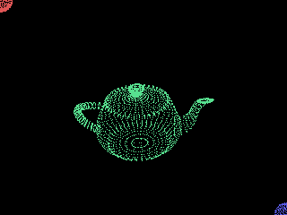
Here is what the camera sees when rendering the view - notice the red and blue spheres appearing exactly where expected:

world_size = screen_origin-end_screenNow we know the two extremes of the projection plane and can calculate the width and height of the projection plane in world units. We also know the size of the plane in pixels, so we can determine the relationship between pixels and world units!
x_aspect = screen_width/(abs world_size.x)
y_aspect = screen_height/(abs world_size.y)
Using the size of the plane, we can calculate the aspect values - basically the number of pixels corresponding to one world unit along X and Y.
screen_coords= point2 (x_aspect*(thePos.x-screen_origin.x)) (-(y_aspect*(thePos.y-screen_origin.y)))Using the aspect values, we can convert the X and Y values of the vertex position into actual pixel positions. Note that the Y coordinate is inverted, and the X position has to be offset by the screen_origin because the camera axis (the center of the image) is located at coordinates [0,0], while the actual origin of the image in MAXScript is in the upper left corner...
setPixels front_vfbscreen_coordsdot_colorNow we can draw a pixel in the front buffer at the location of the current vertex using the color array defined above using the wireframe color.
)--end v loop
)--end o loop
display front_vfb
When all vertices of all objects have been processed, we can update the display.
et = timestamp()Then we can stop the time again to see how long it took to draw once.
pushPrompt ("VertRender " +(1000.0/(et-st)) as string + " fps")The result will be output to the status bar.
)--end fn
on isChecked returnVertexRendererEnabled
When the macroScript is placed on a toolbar, menu or QuadMenu, its checked status will be determined by the boolean value stored in the local variable we defined in the beginning...
on execute do (When the user presses the button / selects the menu item...
VertexRendererEnabled = not VertexRendererEnabled...we flip the state of the variable - if it was true it becomes false and vice-versa.
if VertexRendererEnabled then
(
If the script was just enabled, then
screen_width=RenderWidth
screen_height=RenderHeight
we read the current size values of the Render Scene dialog. You could replace these values with your fixed values, for example 320 and 240 to have a fixed size regardless of the renderer settings...
back_vfb = bitmap screen_width screen_height
front_vfb = bitmap screen_width screen_height
Then we use these size values to define two bitmaps. The first is the back buffer used to clear the image before drawing. Once again, you could use an openBitmap call here to load a background image from disk to draw on top of it!
registerRedrawViewsCallback VertexRendererFunctionHere we register the function we defined above as a viewport redraw callback. Each time the 3ds Max viewport is redrawn, the function will be called and update the rendered image!
VertexRendererFunction() To initialize the display, we call the function once.
)
else
(
unRegisterRedrawViewsCallback VertexRendererFunction
If the renderer was already open, it has to close now. We unregister the callback function to avoid further updates,
close front_vfb and close the image to undisplay it.
)
)--end on execute
)--end script