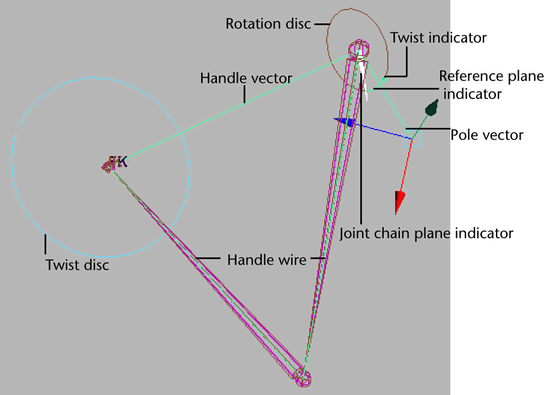
The rotate plane solver is ideal for posing joint chains (such as arms and legs) that you want to stay in the same plane. For example, the shoulder, elbow, and wrist joints of an arm driven by a rotate plane IK handle all stay within the same plane as the elbow rotates. The plane itself can be rotated from the shoulder joint by the pole vector.

A rotate plane IK handle uses the rotate plane solver to calculate the rotations of all the joints in its IK chain, but not the joint chain’s overall orientation. Instead, the IK rotate plane handle gives you direct control over the joint chain’s orientation via the pole vector and twist disc, rather than having the orientation calculated by the IK solver. The single chain solver and rotate plane solver differ in this respect. See also Difference between single chain and rotate plane IK handles in the topic IK solvers.

See also Pole vector and Twist disc descriptions, below.
Rotate Plane IK handle components
- Twist disc
-
The twist disc is a manipulator that you can use to twist or rotate the joint chain. The twist disc is located at the end joint of the IK chain.
Translating the pole vector often leaves the IK chain pointing in the wrong direction. You can use the twist disc to re-orient the plane after you move the pole vector to prevent flipping.
- Joint chain plane
-
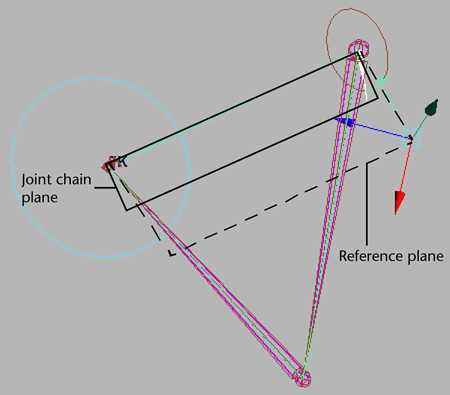
The joint chain plane is the plane that contains all the joints in the joint chain and poses through the axis. The joint chain plane rotates about the handle vector. When you manipulate the pole vector, you are rotating the joint chain plane about the handle vector.
- Reference plane
-
For the joint chain plane to rotate and twist the joint chain, the plane must rotate relative to some other plane so that the degree of twist can be measured. The plane that the joint chain plane rotates relative to is the reference plane.
- Pole vector
-
The pole vector is a manipulator that lets you change the orientation of the IK chain. The pole vector also lets you control flipping.
Since moving the pole vector changes the orientation of the reference plane, moving the pole vector can also change the orientation of the joint chain directly; just as manipulating the twist disc can change the orientation of the joint chain. This is because the joint chain’s degree of orientation—or twist—is defined as the difference in orientation between the reference plane and the joint chain plane.
Important: When positioning your IK handle, if the handle vector and the pole vector cross each other or point in exact opposite directions, the joint chain can suddenly flip. You can prevent this flipping by moving the pole vector so that the handle vector does not cross it or point in the opposite direction from it.
Rotation disc
The rotation disc is an indicator that displays how much the IK chain has been rotated by the twist disc. The rotation disc is located at the start joint of the IK chain.
- Reference plane indicator
-
The reference plane indicator is the green dot on the rotation disc that moves to reflect the movements of the pole vector.
- Twist indicator
-
The twist indicator is the green arc between the reference plane indicator and the joint chain plane indicator on the rotation disc. The twist indicator displays the orientation of the joint chain relative to the reference plane.
- Joint chain plane indicator
-
The joint chain plane indicator displays the orientation of the joint chain plane relative to the reference plane. The joint chain plane indicator appears in the rotation disc.