
You can set the following preferences in the Animation sub-category in the Settings category in the Preferences window.
See also Edit animation preferences.
To return to the default factory settings, choose in this window. Note that this resets the preferences in every category in the Preferences window.
Evaluation
Select an evaluation mode to increase playback performance.
- DG
- Uses dependency graph-based evaluation mode for your scene. (See also Dependency graph.) This was the default evaluation mode before Maya 2016.
- Serial
- Uses the Evaluation Manager but limits evaluation to a single core (serial evaluation). Use
Serial to troubleshoot your scene as it prioritizes scene fidelity over performance so you can locate evaluation errors.
Note: Sometimes scenes run more slowly in Serial evaluation mode than in DG mode. This is because Serial evaluates more nodes than DG mode. Because of this detailed evaluation, if the scene looks incorrect in Serial mode, it is unlikely to work properly in Parallel mode.
Sometimes improper evaluation in Serial mode is caused by custom plug-ins.
- Parallel
- Parallelizes evaluation and uses all available cores to evaluate your scene. If this mode causes problems with your scene, disable it and return to the previous standard: DG evaluation mode. This mode is active by default.
- GPU Override
- Works with the Evaluation Manager to accelerate deformations in either
Serial or
Parallel Evaluation mode. If your scene has standard
Maya deformers and the mesh geometry is dense, this can improve performance. Results vary based on the deformers and density of meshes in your scenes.
Note: GPU override works only with Viewport 2.0 and does not work with Quadro 4000 graphics cards on OSX.
- You can find a technical explanation of GPU Override at Using Parallel Maya.
- Include Controllers in Evaluation Graph
- Activates/disables pre-population with the controller mechanism in the Evaluation Manager when building.
For more detail on how these modes work and other performance optimization tips, see Increase perfomance with the Evaluation Manager.
Auto Key
- Auto key
-
Specifies whether Maya will automatically set keys on a previously animated object’s attributes when you change the values of those attributes. This preference has the same effect as the Animation Controls’ Auto Keyframe Toggle button
 (next to the
Animation Preferences button
(next to the
Animation Preferences button
 ). This option is off by default.
Note: Once turned on, Auto key reads the minimize rotation attribute of the keying group object created with the HIK rig.
). This option is off by default.
Note: Once turned on, Auto key reads the minimize rotation attribute of the keying group object created with the HIK rig.
On character sets
These options are available only when Auto Key is on.
For more information, see Character Sets.
- Key Modified Attributes
-
Sets keys only for attributes that have been modified.
- Key All Attributes
-
Sets keys for all attributes, whether they have been modified or not.
Rotation Interpolation
To set the rotation interpolation options, see Set rotation interpolation for curves.
- New curve default
-
Specifies the type of rotation interpolation used when creating curves. These options are the same as those available in the Change Rotation Interp menu item in the Graph Editor Curves menu. For more information on rotation interpolation, see Animated rotation in Maya.
- Independent Euler
-
Calculates the rotation using three separate angles representing rotations about the X, Y, and Z axes, and an order or rotation. In this mode, the curves that define the rotation for a given node are represented in Euler-angles, interpolation is performed on each curve independently in Euler space, and keyframes may occur at your discretion—they are not synchronized with the other sibling rotation curves at the node. You can also animate a single rotation ordinate. This is the default setting.
- Synchronized Euler
-
Creates curves that have keyframes on sibling curves locked together but with interpolation between keyframes performed in Euler-space.
It’s useful to keep rotation keyframes synchronized because rotation is a composition of the three separate rotate values. Deleting just one key on a curve can have a dramatic and unexpected effect on the interpolation.
- Quaternion Slerp
-
Interpolation is calculated using spherical linear interpolation and does not depend on the tangents of the input curves.
- Quaternion Cubic
-
Interpolation is calculated using quaternion cubic interpolation (Squad) and does not depend on the tangents of the input curves.
- Quaternion Tangent Dependent
-
Interpolation is calculated using quaternion interpolation based on the input curve tangents. For example, if the tangents are linear, Maya uses spherical linear interpolation (Slerp), and if the tangents are clamped, Maya uses cubic interpolation (Squad).
- New HIK curve default
-
Let you set the default rotation interpolation type for new HIK curves. This drop-down list contains the same set of rotation interpolation options as the New curve default preference (listed above). The default for HIK curves is Quaternion Slerp.
Tangents
Tangents determine the status of curve segments when they enter and exit from a key.
- Default tangent weight
-
(Formerly called Weighted Tangents in previous versions of Maya)
Default tangent weight represents the amount of influence a tangent has on an animation curve segment. Select between Weighted or Non-weighted:- Weighted tangents
-
Weighted tangents: you can change angle and length
- Weighted tangents have long handles that let you edit the influence and angle of the tangent quickly and intuitively, similar to Bezier-style behavior in vector-based graphics software. Weighted tangents let you manipulate both tangents on a key, keeping the arc of the curve balanced on both sides.
- Non-weighted tangents
-
Non-weighted tangents: you can change angle but not length
- Non-weighted tangents have simple handles that only control the tangent's angle.
See Edit tangents.
- Default in tangent
-
Specifies the default in tangent type. The In Tangent setting controls the shape of the animation segment before a key.
Options include:
- Auto
-
(Default) An Auto In Tangent compares the current keyframe value to the previous keyframe value, and flattens the curve segment if it travels above or below those keyframe values. (See also Auto Tangents in the Graph Editor Tangents menu.)
- Spline
-
A spline tangent rounds the animation curve smoothly before the key. If the key’s Out Tangent is also a spline, the tangents of the curve are then co-linear (both at the same angle). This ensures that the animation curve smoothly enters and exits the key.
- Linear
-
A linear tangent creates an animation curve as a straight line before the key.
- Clamped
-
The clamped tangent smoothly rounds the animation curve (like the Spline selection) before a key unless the next key is very close. If so, the In Tangent and the previous key’s Out Tangent are both straight (like the Linear selection), making the animation curve between the keys straight.
- Flat
-
A flat tangent type sets the tangents before the key to be horizontal with a slope of 0 degrees (flat).
- Plateau
-
A plateau tangent type eases animation curves in and out of their keyframes, flattens curve segments that occur between equal-valued keyframes, flattens keyframes at the points in their curves where hills and valleys occur, and flattens the first and last keyframes on their curves.
- Default out tangent
-
Specifies the default out tangent type. The Out Tangent setting controls the shape of the animation curve right after a key.
Options include:
- Auto
-
(Default) An Auto out tangent compares the current keyframe value to the next keyframe value, and flattens the curve segment if it travels above or below those keyframe values. (See also Auto Tangents in the Graph Editor Tangents menu.)
- Spline
-
A spline out tangent rounds the animation curve smoothly after the key. If the key’s In Tangent is also a spline, the tangents of the curve are then co-linear (both at the same angle). This ensures that the animation curve smoothly enters and exits a key.
- Linear
-
A linear tangent creates an animation curve as a straight line after a key.
- Clamped
-
Specifies the animation curve is smoothly rounded (like the Spline selection) after a key unless the next key is very close. If so, the Out tangent and the previous key’s In tangent are both straight (like the Linear selection), making the animation curve between the keys straight.
- Flat
-
A flat tangent type sets the tangents after the key to be horizontal with a slope of 0 degrees (flat).
- Stepped
-
A stepped tangent type forces the animation curve to hold its value from the one key to the next key.
- Plateau
-
A plateau tangent type eases animation curves in and out of their keyframes, flattens curve segments that occur between equal-valued keyframes, flattens keyframes at the points in their curves where hills and valleys occur, and flattens the first and last keyframes on their curves.
Animation Blending
The Animation Blending preferences let you specify the types of blends that can occur between object connections. For example, when you turn on Always blend with existing connections, you can then both animate and constrain a single object.
Blend
- Always blend with existing connections
-
When this preference is on:
- You can move or key objects that have existing connections such as animation and constraints.
- When you key or constrain an object, Maya inserts a pairBlend node between the object’s existing connections and the new keys or constraints.
- The Lock Output attribute is off by default for all new constraints.
- Always Blend with Existing Connections is on by default.
- Blend with all except constraints
-
When this preference is on:
- You can only key objects that are not constrained.
- When you key an object, Maya inserts pairBlend nodes between the object’s existing connections and the new keys.
- Objects with connections cannot be constrained.
- The Lock Output attribute is on by default for all new constraints.
- Never blend with existing connections
-
When this preference is on:
- You can only key objects that have no existing connections.
- Maya does not insert pairBlend nodes to blend object connections.
- The Lock Output attribute is on by default for all new constraints.
AnimBlendNode
The AnimBlendNode options let you specify the types of blends that can occur between object connections when one of its sources is disconnected. This is useful if you want to use the input from the remaining connection as the output. That is, if inputA's connection is broken, then use inputB's result as the output. This sets the input with broken connection to 0, instead of the current value.
This applies only if you explicitly disconnect or delete a paramCurve node on a specific animLayer.
- Reset to Current Value on Broken Input
- Retains the actual value.
- Reset to Identity on Broken Input
- Resets the value to what is referred to as "identity". In most cases, this value is 0 except for scaling, where is it 1.
Graph Editor
- Snap Value to Adjacent Keys
- When on (default), neighboring keys with similar values automatically align as you edit curves in the Graph Editor. Enable this preference if you want similar, adjacent keys to snap to identical values.
- Left-dragging moves selected keys

- When on (default), you can drag to move selected keyframes in the Graph View area with a single click.
- When off, left-clicking only select keys which is useful if you don't want to move keys accidentally when the selection region is close to a key or tangent, which happens when working with dense keys/tangent networks.
- Have this option on is preferable for people familiar with keyframe editing workflows in other Autodesk applications, such as MotionBuilder.
- Use Constant Falloff except for Move and Scale
-
- Activate this option to use a constant falloff for a tool other than Move and Scale.
- This allows for behavior that was previously only in the Classic (pre-Maya 2022) Graph Editor.
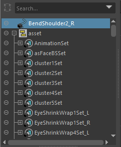
- Display Assets
- Activate this option if you want to show asset containers in Outliner views. This option is off by default
-
When on, shows assets in the following Outliners:
- as well as the following Relationship Editors:
-
Note: If the Graph Editor is docked when you activate the Display Assets option, it will not appear. Undock the Graph Editor from the UI and redock it for the changes to take effect. (For more information see Dock and undock windows and panels.)
- Stacked View Spacing
- Widen or narrow the horizontal "lanes" that stacked curves display in the Stacked view. .2 is the default.
- Auto Frame
- Automatically adjusts the graph view to fit the display of the animation curve associated with a selected object or objects. This option only adjusts to fit the y-axis view. To frame both x- and y-axes, activate this option and the Auto Frame both Axes option, below.
- Auto Frame both Axes
- Auto-frames the graph view in both the x (time) and y (value) axes. This option is only available if the
Auto Frame option (above) is activated.
Tip: You can activate both this and the Auto Frame options from the Graph Editor View menu.
- Key Size
-
Lets you control the size of the keys shown in the Graph Editor Graph View. Key size is percentage of the original key size (100% or a value of 1). You can scale keys between 40% (0.4) and 200% (2).
-
Tip: Use the following command to exceed the default size settings: animCurveEditor -edit -keyScale 0.8 graphEditor1GraphEd;
- Min key selection size
- Lets you set the selection area boundary for selecting keys. Changing this setting is useful if you are unintentionally including keys when drag-selecting in the Graph View. It's a good idea to decrease the boundary size with this setting when working with scenes with dense animation and the Graph Editor is at reduced size so the keys selected are more precise.
Time Editor
The settings pertain to the Time Editor.
- Granularity
- Lets you set a minimum number of attributes for the Time Editor to animate. For example, a setting of 1 creates a separate Clip TRS/Interpolator nodes for each object, while a setting of 100 creates a single Clip TRS/Interpolator node for up to 100 objects.
- Use the Time Editor Granularity setting to tweak the performance of the Time Editor when the default settings perform slowly. Very large scenes in the Time Editor can create many DG nodes which could create performance issues. The Time Editor Granularity setting lets you adjust the "granularity" to create fewer but larger nodes.
- The default setting is 200.
- Snap tolerance
- Set how precisely you want clips to adhere to the nearest object on the track. See Toggle Snap in the Time Editor toolbar topic.
- Minimum clip width
- Lets you specify the smallest screen size that a clip appears on a Track when zoomed out. The default is 8 pixels.
- In-view Messages
-
Turn off this option to hide the informational messages about the state of the Time Editor.
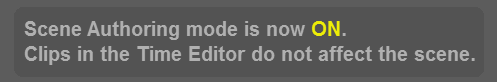
In-View message example
- Allow clip creation to override existing constraints
- If there are existing rig setups in your scene, importing animation for constrained attributes into the Time Editor disables any constraints if the Time Editor is not muted.
- Activate this option to prevent constrained attributes from overridden by the Time Editor when you import a clip.
- Input Audio Rate
-
- Lets you set the sampling frequency of audio clips used in the Time Editor. Setting the audio rate of your file from the drop-down list ensures sound compatibility, particularly when playblasting. See also Add audio to the Time Editor.
Guide Lines
- Time line display
- Choose between:
- Working units, uses the scene's frame rate to determine when a time grid line is shown. For example, if you're working in a scene at 24 fps, you will see a Time line (vertical line) every 24 frames. The increments are based on the value specified in the Preferences window Settings Preferences World Coordinate System section.
- Custom units, which let you specify a value for when a Time line (vertical grid line) is appears. For example, enter 3 in the Units field, and a Time line occurs every 3 frames.
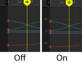
- Automatic, which adjusts Time Lines based on your Graph View zoom level. This is the default setting.
The Automatic setting increases the Time lines as you zoom
- Time line start
- Enter a value for the position of the Time line display start frame. For example, if you have a line every 24 frames, and you set the start to 1, a Time line appears on frame 1, and on frame 25.
- Value line display
- Toggles the visibility of values along the right side of the Graph view. The default is
On.
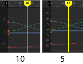
- Value line interval
- Lets you set the spacing of values along the right side of the Graph view. The default is
10.
Rigging
This section has settings for componentTag nodes. which replace groupID nodes, and lets you create node-independent named groups to deform geometry. Component Tags let you modify tag membership as you work as well as clean up the Node Editor by eliminating unnecessary nodes.
See Assign Component Tags to geometry and Component Tags table for information on working with Component Tags.
- Component Tags
-
- Uses Component Tags for deformation component subsets.
- Activate this option to convert selected geometry to a Component Tag. When this option is tuned on, the option below (Convert component selection to a Component Tag on deformer creation), is automatically activated.
- Create Component Tag on deformer creation
- Converts selected components to Component Tags automatically when you create deformers. Disable this option if you do not want this to occur when creating deformers.
- Tweaks
- Adds a
Tweak node whenever a deformer is added to the scene. By default, this setting is off, and no Tweak nodes are created when you add deformer to geometry. Adding a Tweak node to deformed geometry lets you store edit information such as mesh modifications, vertex repositioning, so that if you disable the deformer, the edits are not retained.
Note: Tweak nodes are not automatically created when you use Component Tag nodes. See Assign Component Tags to geometry and Add Tweak in the Deform menu.
- Weights Color
-
- Use these settings to customize the deformer falloff color ramp. For information on how to show falloff weighting as colors, see Visualize deformer weights. You can use a color ramp for more nuanced weighting feedback and/or set only a maximum and minimum color for weight limits.
-
- Out of Range Color
- Choose a color to alert you when the falloff has gone past its range of influence.
- Use Max/Min Color
- Turn on this option to customize colors for weight limits.
Option Function Min color The color used to show weighting at the lowest end of the deformation spectrum. Max color The color used to show weighting that has reached its upper limit. - Use Color Ramp
- Turn on this option to enable color ramp settings that define the span of the weighting falloff.
-
- Color Ramp
- Use the Color Ramp to tweak the color gradient used for the falloff weight ramp.
-
Click and drag the circular color handle above the ramp to reposition it. To add a color to the ramp, double-click inside the gradient field, and to change a color, select a circular color handle and use the Selected color swatch, below.
- To delete a color from the ramp, click the square beneath the ramp.
- Selected color
- Double click the color swatch to open the Color Chooser to set a specific color for the Color Ramp.
- Color Presets
- Choose from three color preset color ramps or create your own using the Color Ramp, above.
Camera Sequencer preferences
Shot Double Click
This preference lets you set what you want to occur when you double-click a camera shot in the Camera Sequencer.
- Set Maya Frame Range
-
Set the frame range in the Time Slider to match the Maya start frame and Maya end frame of the selected shot. (See Camera shot overview.)
- Select Camera
-
Select the camera assigned to the selected shot.
- Frame Sequencer to Shot
-
Frame the selected shot in the shot view area.
- Solo Track
-
Turn on the Solo option for the track containing the selected shot.
- Don't Modify Sequence Time
-
Select to keep the Sequence Time indicator at the current time, regardless of where you double-click.
- Set Sequence Time To Cursor
-
Select to have the Sequence Time indicator jump to where you double-click.
- Set Sequence Time To Shot Start
-
Select to have the Sequence Time indicator jump to the start of the selected shot.
- Set Timeline Min/Max to Shot
-
Sets the timeline's min/max frames to the Shot's time range values.
- Set Timeline Min/Max to Sequencer
-
Sets the timeline's min/max frames to the Sequencer's time range values.
- Don't alter Timeline Min/Max
-
Does not set the timeline's min/max frame values.