Using the Advanced Gate Locator algorithm
In this task, you will use the Advanced Gate Locator algorithm to analyze a part and automatically place a gate onto a copy of the model.
Create a new project and import the cellphone.stl tutorial file, located in the tutorial files you saved.
The Advanced Gate Locator algorithm locates optimal injection locations based on minimizing the flow resistance.
Click
 (Home tab > Molding Process Setup panel > Analysis Wizard).
Select the Sequence tab, and select the Gate Location checkbox.
Note: You may need to deselect other analysis sequences to allow the Gate Location analysis to be selected.Select the Gate Location tab, and choose Advanced Gate Locator from the drop-down menu.
Enter 2 in the Number of gates text box, then select Finish.
You can also select regions of the model where you do not want to allow injection locations.
The default selection method is using a tolerance angle. Adjacent areas are selected when they meet at an angle less than the tolerance angle. By increasing the tolerance angle, or selecting a number of regions, you can prohibit injection locations from being placed on the front face of the cellphone cover.
Tip: An extra result is available when you set the Number of Gates to be 1 using the Advanced Gate Locator algorithm. The Gating suitability result rates each place on the model for its suitability for an injection location.Click
 (Home tab > Molding Process Setup panel > Boundary Conditions).
Click
 (Boundary Conditions tab > Injection Locations panel > Prohibited Gate Regions).
The Tools tab displays the Prohibited Gate Regions pane.
Enter a Tolerance of 35 degrees.
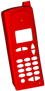
Click on the front face of the model to prohibit injection locations from being placed on this surface.
You may need to select multiple regions to prohibit the entire front face of the cellphone as there are several fillets.
Prohibited regions are displayed in red.

Click Close.
Click (Boundary Conditions tab > Exit panel > Finish Boundary Conditions).
Prohibited gate regions will be ignored when you run the Gate Location analysis.
Select the Tasks tab to show the Study Tasks pane.
Click
 (Home tab > Analysis panel > Analyze) to run the Gate Location analysis.
Click OK when the analysis is complete.
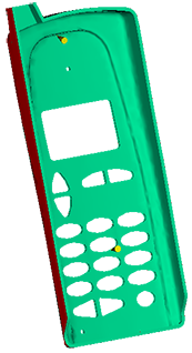
The result produced shows the recommended injection locations.
Click Summary in the Study Tasks pane, then click the Gate Location tab.
Click Apply All to place an injection location using the Shape and the Coordinate specified in the New Gate Locations table.
Click Create Copy.
A new study is created, containing two injection locations.

You can now run a Fill analysis to check how your part fills.
Parent topic: Gate Locator algorithms (tutorial)
Next topic: Using the Gate Region Locator algorithm