Apply the Constraints
- In the tree view, right-click on Constraints under Subcase 1 and choose New.
- Select all the side faces of the die except the contacting face, and also select the slab end face as shown in the image below. Click on the
Fixed button.
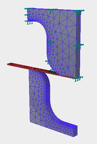

- Be sure that Subcase 1 is selected in the Subcases list.
- Click on
 New button.
- Change the color to Brown.
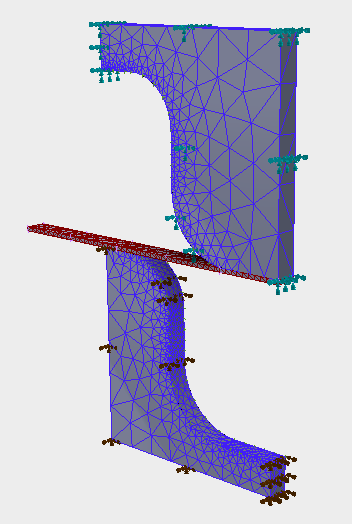
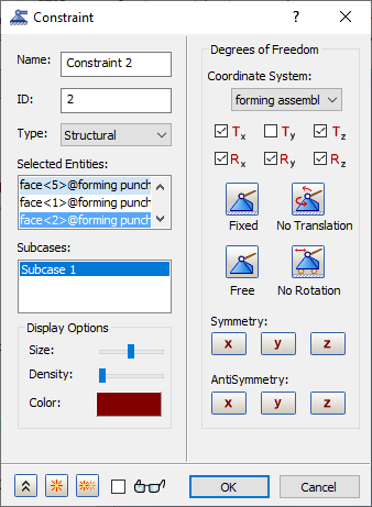
- Select all the side faces of the punch model except the contacting face. Click on the
Fixed button and unselect
Ty as shown in the image below.
- Click on
 New button.
- Change the color to Yellow.
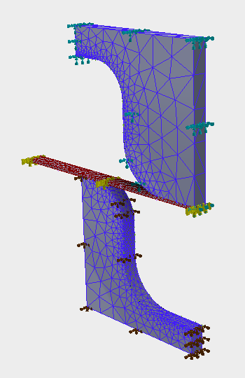
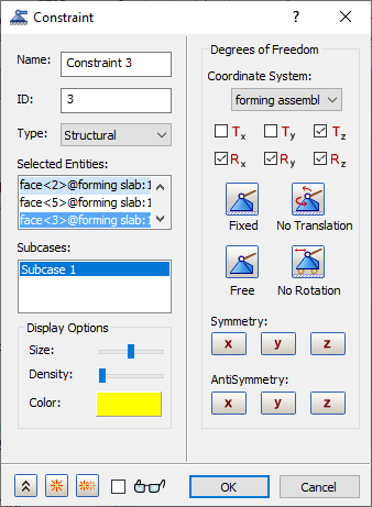
- Select all the faces of the slab model except the fixed end. Uncheck
Tx and
Ty as shown in the image below.
- Click on
 New button.
- Change the color to Red.
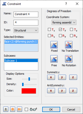
- Select the bottom face of the punch model. Click on the
Free button and select
Ty as shown in the image below.
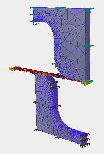
- Click OK to create the constraint in Y direction for the enforced displacement load.
Apply the Loads
- Right-click on Loads under Subcase 1 and choose New.
- Change the Name to Displacement.
- Select Enforced Motion as load Type and select Displacement as Sub Type.
- Enter
0.8 for
Ty and select the bottom face of the punch model where the constraint in Y direction is fixed.
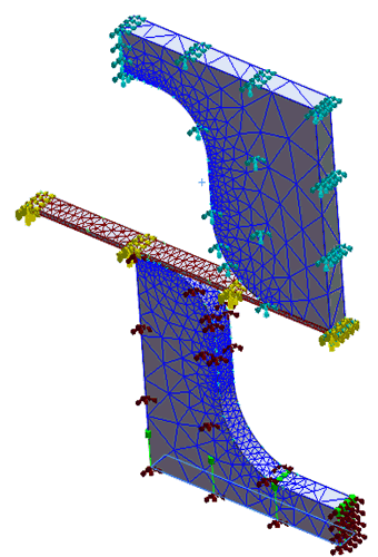
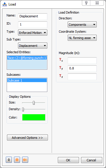
- Be sure that Subcase 1 is selected in the Subcases list.
- Click OK to create the displacement load.
Create the Surface Contacts
- In the Model tree, right-click on Surface Contacts and choose New.
- Change the Name to Top Contacts.
- Click inside the Primary Entity box, then pick the top surface of the sheet slab as the Primary Entity surface.
- Click inside the
Secondary Entity box, then select the contacting face of the die, as shown in the image below.

- Make sure Add to Analysis is checked, and in Contact Data, the Penetration Type is Unsymmetric Contact.
- Enter
0.2 for the
Stiffness Factor, and
0.02 for the
Coefficient of Friction.

- Click on
 Duplicate button and change the
Name to
Bottom Contacts.
- Clear all the entities and re-select the
Primary Entity as the bottom surface of the sheet slab and
Secondary Entity all the contacting faces of punch model, as shown in the image below. Verify that the values for
Penetration Type,
Stiffness Factor, and
Coefficient of Friction are the same as used for the Top Contacts.
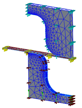

- Click OK to create the surface contacts.