Surface inspection groups enable you to inspect non-geometric surfaces on a part, and to compare the results with the CAD model. You can display the results in the CAD view using the Inspection Point Display options in the View Options panel of the View ribbon tab, or view detailed information about each point using the Report and Info tabs below the Graphics window.
To create a surface inspection group:
- Click Home tab > Create panel > Form > On-the-Fly Surface Group.
The Inspection Group: Surface Points dialog is displayed. It enables you to specify the type of points to be taken, the method to be used to take the points, the naming rules for the points, tolerances, and so on.
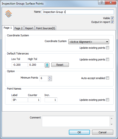
- Ensure the Output in report check box is selected.
This enables you to display the measurements as labels in the CAD view, and in the report.
- By default, you must measure a minimum of six points for a surface inspection group, but you can change this value to suit the surface you want to measure. Enter 8 in the Minimum points box to specify the minimum number of points to be measured on this surface.
- Click OK to add the group to the inspection sequence.