You can create PCF files without creating Iso drawings. You can also create Iso drawings directly from PCF files.
When you generate an isometric drawing from the model, a Piping Component File (PCF) is automatically created. Even if you are not generating an isometric drawing, you can export a PCF if you need one for the stress engineer or pipe fabricator.
You can later import the PCF file to create an isometric drawing. You can also import a PCF file that is created from another program.
To export a PCF file
- On the ribbon, click Isos tab
 Export panel PCF Export.
- In the Export PCF dialog box, select the Line numbers to export.
- Click Create.
A separate PCF file is created for each line number selected.
To create an Iso drawing from a PCF file
- On the ribbon, click Isos tab Iso Creation panel PCF to Iso.
- In the Create Iso from PCF dialog box, click Add.
- Specify one or more PCF files to create isometric drawings from.
- Click Create.
To import a PCF file into the 3D model
- On the ribbon, click Home tab Part Insertion panel PCF to Pipe.
- Specify one or more PCF files to import (for example:
\Isometric\Live Preview\Sample PCF\SampleIsoPreview.pcf) and click Open. The PCF to Pipe dialog box displays.
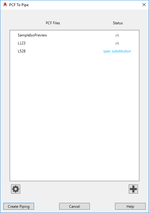
- If
spec unavailable displays in the Status column do the following:
 Click the settings button. The PCF to Pipe Settings dialog box displays.
- In the Plant 3D Spec column, click on a project spec to match the PCF spec.
- Repeat until all Plant 3D specs are assigned.
Note: The placeholder spec is used for any PCF specs not mapped (spec unavailable).
- Click OK
- If you prefer not to import a PCF file that could not map to a project spec, click the
 Remove button.
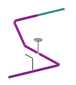
- Click Create Piping.
For example, the PCF used in the Live Preview adds piping, fittings, and valves to the model.