Controls the type of errors that are flagged.
 Ribbon: Home
  Validate tab Validate Config (for P&ID workspace)
 Shortcut menu: Project Manager Right-click the project node Validation Settings
Right-click the project node Validation Settings Command entry: validateconfig
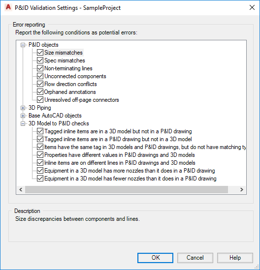
Error Reporting
Controls the type of errors that are flagged by the validation program.
- P&ID objects
-
Specifies which types of P&ID errors are flagged. The following options are available:
- Size Mismatches. Identifies size discrepancies in components and lines.
- Spec Mismatches. Identifies discrepancies in the specifications of components and lines.
- Non-terminating Lines. Identifies lines that do not connect to components, or do not have a termination symbol.
- Unconnected Components. Identifies components that are not connected to a line at all its attachment points. If a component has no attachments points, at least one line must be connected to it.
- Flow Direction Conflicts. Identifies errors in the direction in which materials flow through lines.
- Orphaned Annotations. Identifies annotations that have moved beyond the tolerance threshold of their associated components.
- Unresolved Off-page Connectors. Identifies off-page connectors that do not continue on another drawing in the same project.
- 3D Piping
- Specifies which types of Plant 3D errors are flagged. Note: To see disconnection markers in the model, on the Home tabThe following options are available:Visibility panel, click the Toggle Disconnect Markers icon
 .
.
- Disconnected port Identifies Plant 3D parts that are disconnected.
- Placeholder parts. Identifies Plant 3D placeholder parts.
- Property mismatches. Identifies Plant 3D property mismatches.
- Base AutoCAD Objects
- Specifies which types of AutoCAD errors are flagged. The following options are available:
- All AutoCAD Objects. Identifies the presence of any type of AutoCAD object that could be misinterpreted as P&ID symbols.
- Lines. Identifies AutoCAD lines that could be misinterpreted as P&ID schematic lines.
- Polylines. Identifies AutoCAD polylines that could be misinterpreted as P&ID schematic lines.
- Circles. Identifies AutoCAD circles that could be misinterpreted as instrument bubbles.
- Annotations. Identifies AutoCAD text, multiline text (mtext), leaders, dimensions, attributes, and tables that could be misinterpreted as P&ID annotations.
- Blocks. Identifies AutoCAD xrefs, blocks, and dynamic blocks that could be misinterpreted as P&ID components.
- 3D Model to P&ID checks
- Specifies which types of mismatches between the 3D Model and the P&ID drawing are flagged. The following options are available:
- Tagged inline items are in a 3D model but not in a P&ID drawing. Identifies Plant 3D objects that exist in the model but not in the P&ID drawing.
- Tagged inline items are in a P&ID drawing but not in a 3D model. Identifies Plant 3D objects that exist in the P&ID drawing but not in the 3D model.
- Items with the same tag are different types in 3D models and P&ID drawings. Identifies items that have identical tags but are different types.
- Properties have different values in P&ID drawings and 3D models. Identifies items that have different property values. For example, a pipe is 6” in the P&ID drawing and 4” in the 3D model.
- Inline items are on different lines in P&ID drawings and 3D models. Identifies where matching inline components are on different lines in the P&ID drawings and 3D models. For example, a gate valve is on l-100 in the P&ID drawing and on l-200 in the 3D model.
- Equipment in a 3D model has more nozzles than it does in a P&ID drawing. Identifies extra nozzles in the 3D model that do not exist in the P&ID drawing.
- Equipment in a 3D model has fewer nozzles than it does in a P&ID drawing. Identifies extra nozzles in the P&ID drawing that do not exist in the 3D model.
Description
Provides information about the selected error condition.