You can change parameters for lighting fixtures and their light sources when defining a lighting fixture in the Family Editor, or when modifying a lighting fixture in a building model.
| Parameter | Description |
|---|---|
| Electrical - Lighting | |
| Calculate Coefficient of Utilization (default) | A value used to indicate that the Coefficient of Utilization will be calculated for the lighting fixture by default. In a project, you can change this default behavior by changing instance properties. |
| Coefficient of Utilization (default) | A value used to define the efficiency of a lighting fixture in transferring luminous energy to the work plane in a particular area. This value shows the percentage of lumens that reach the work plane after light is lost due to the fixture’s efficiency at transmitting light, the room proportions, and the ability of room surfaces to reflect light.
If you select Calculate Coefficient of Utilization (default), this parameter is read-only. If you clear Calculate Coefficient of Utilization (default), you can enter a value between 0 and 1, or enter a formula. In a family, this parameter defines the default value for the lighting fixture. In a project, you can change the default in instance properties. |
| Electrical - Loads | |
| Apparent Load | A value used to define the real and reactive power used by a fixture. To determine Apparent Load, multiply the apparent current by the voltage. This parameter is measured in volt amps (VA). |
| Dimensions: These parameters do not affect rendered images. | |
| Light Source Symbol Size | The size of the symbol that represents the light source in 2D and 3D views, extending from the boundary of the Emit from Shape outwards. For example, suppose you define a light source with an Emit from Shape of circle and an Emit from Circle Diameter of 500 mm. If you specify a Light Source Symbol Size of 200 mm, in a 2D view,
Revit shows a light source symbol that is 900 mm in diameter (200+500+200). This parameter is available when the Emit from Shape setting is Circle or Rectangle. (See
Define the Geometry of a Light Source.)
This parameter does not affect the light in a rendered image. |
| Light Source Symbol Length | The length of the symbol that represents a spotlight in 2D and 3D views, extending from the spotlight outwards. This parameter is available when the Light distribution setting is Spot.
This parameter does not affect the light in a rendered image. 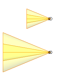 Spotlights with different light source symbol lengths (plan view) |
| Identity Data | |
| Keynote | Keynote for the lighting fixture. Enter text or click
|
| Model | Model number or code assigned to the lighting fixture by the manufacturer or vendor. |
| Manufacturer | Name of the manufacturer of the lighting fixture. |
| Type Comments | User-defined comments or other information about this family type for the lighting fixture family. |
| URL | URL of the Web site for the manufacturer or vendor. |
| Description | Description of the lighting fixture. |
| Assembly Code | Uniformat assembly code for the lighting fixture. |
| Cost | Cost of the lighting fixture. |
| Electrical: These parameters do not affect rendered images. | |
| Ballast Voltage | Voltage required to operate the ballast. A ballast is an electrical device that provides the starting voltage and limits the current to sustain lamp operation. |
| Ballast Number of Poles | The number of leads in the circuit. Enter 1, 2, or 3. |
| Lamp | Number and type of light bulbs used in the lighting fixture. (This information can be useful in schedules.) |
| Wattage Comments | User-defined information about wattage requirements for the lighting fixture. |
| Photometrics: The following parameters affect rendered images. You may be able to obtain parameter values from the manufacturer of the light source. Check the manufacturer’s website. | |
| Photometric Web File | The IES file that defines the light emitted from the light source. This parameter is available when the Light distribution setting is Photometric Web.
To specify a file, click in the Value column, and click
Note: Revit does not maintain a link to the IES file. If you change or update the IES file on disk, you must also update this parameter by navigating to the new version of the file.
|
| Spot Tilt Angle | The angle to tilt the light source to direct its light. Enter a value between 0 and 160. This parameter is available when the Light distribution setting is Spot or Photometric Web. |
| Spot Field Angle | The angle at which the light intensity reaches 10% of the peak intensity. Enter a value between 0 and 160. This parameter is available when the Light distribution setting is Spot. |
| Spot Beam Angle | The angle at which the light intensity reaches 50% of the peak intensity. This parameter is available when the Light distribution setting is Spot. |
| Light Loss Factor | A value used to calculate the amount of light lost (or gained) due to environmental factors, such as dust and ambient temperature. Click in the Value field to display the Light Loss Factor dialog. |
| Initial Intensity | Brightness of the light before environmental factors reduce or change the quality of the light. Click in the Value field to display the Initial Intensity dialog. |
| Initial Color | The color of the light source before it is affected by color filters and environmental factors. Click in the Value field to display the Initial Color dialog. |
| Emit from Circle Diameter | The diameter of the light source that emits light in a rendered image. This parameter is available when the Emit from Shape setting is Circle. |
| Emit from Rectangle Width | The width of the rectangle that represents the light source in a rendered image. This parameter is available when the Emit from Shape setting is Rectangle. |
| Emit from Rectangle Length | The length of the rectangle that represents the light source in a rendered image. This parameter is available when the Emit from Shape setting is Rectangle. |
| Emit from Line Length | The length of the line that represents the light source in a rendered image. This parameter is available when the Emit from Shape setting is Line. |
| Emit Shape Visible in Rendering | Select this option to make the shape of the light visible as a self-luminous surface (glow) when the camera (of the 3D view) is aimed directly at the light source. This parameter is available when the Emit from Shape setting is Rectangle or Circle.
Tip: If the Emit from Shape setting is Point or Line, the light source does not display a self-luminous surface in rendered images. To see the light source in rendered images, use a thin rectangle shape or a small circle shape instead.
|
| Dimming Lamp Color Temperature Shift | Specify whether the color and intensity of a dimmed light source change based on predefined curves. For example, incandescent lights typically become more yellow when dimmed. Select Incandescent Lamp Curve or none.
To see the effect of this parameter, you must dim lights in the building model. See Dimming Lights. |
| Color Filter | Color used to change the light emitted from the light source. Click in the Value column. In the Color dialog, select the desired color, and click OK. |