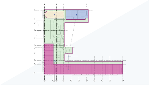
Learn about the electrical analysis tools in Revit. These tools provide electrical engineering load estimating workflows directly within Revit and allow you to use Revit earlier in the process where design analysis and key decisions are made.

What is Electrical Analysis?
- Define electrical analytical loads
- Define analytical system components
Why should you use it?
This functionality was released in Revit 2023 and provides a way for electrical designers and engineers to capture electrical design requirements natively within Revit, reducing dependence on workflows that rely on maintaining data in spreadsheets, PDFs, and other disconnected repositories.
The electrical analysis workflow is designed to allow you to utilize linked DWGs or PDFs, or Revit models as the basis of load takeoffs within Revit. These load takeoffs, along with new capabilities to conceptually define electrical system elements, allow you to determine preliminary building load and load on main equipment components directly within the Revit environment. Use these takeoffs to produce documentation and schedules to communicate design concepts to stakeholders.
Where do you find the tools and how do you use them?
Electrical Analysis tools are located on the Analyze tab of the ribbon. For details on how to use the tools, see Workflow: Electrical Analysis or watch the workflow videos on the Autodesk Building Solutions YouTube channel listed below.
Videos
Step 1: Define conceptual power loads
Step 2: Define conceptual distribution for load analysis