You can draw horizontal and vertical ducts in a plan view.
 Video: Match Size or Elevation for a Duct
You draw a vertical segment of duct in a plan view by changing the Offset value on the Options Bar while drawing a duct segment. However, it is often easier to draw vertical duct segments in an elevation view or a section view. See Drawing Ductwork In an Elevation or Section View.
- Open a view containing the duct system where you want to place ducts.
- Click Systems tab
 HVAC panel
 Duct or
 Duct Placeholder.
- In the Type Selector, select the duct type.
- Optionally, in the Properties palette, under Mechanical, select a system type.
- On the Options Bar, specify
layout options.
Optionally, to draw a vertical duct, on the Options Bar specify an Offset that is above or below the start point, and click Apply. A vertical segment is automatically created, extending from the original offset to the newly applied offset. You can draw horizontal segments to continue the run at the new offset, or click Modify to place only the vertical segment.
- On the ribbon, verify that Tag on Placement is selected to tag the duct automatically. Then specify the following tagging options on the Options Bar:
If you want to... then... change the orientation of the tag select Horizontal or Vertical. load additional tags click Tags. include a leader line between the tag and the duct select Leader. change the default length of the leader enter a value in the text box to the right of the Leader check box. - On the ribbon, select placement options.
- Specify the start point for the duct, move your cursor to the desired duct end location, and click again to specify the endpoint of the duct.
The duct snaps to a
![]() (connector) on a piece of mechanical equipment, duct, duct fitting, or air terminal, or to the centerline of the existing ductwork to establish a starting or ending point for the duct.
(connector) on a piece of mechanical equipment, duct, duct fitting, or air terminal, or to the centerline of the existing ductwork to establish a starting or ending point for the duct.
Transitions, tees, and elbows are automatically added to the segment for 2-line duct. Placeholder duct is drawn without elbow or tee fittings.
Some components have multiple connectors that display stacked one above another. When drawing duct from a stacked connector, a Select Connector dialog displays to let you specify which connector to use.
If the duct is assigned to a system, the air terminals and mechanical equipment connected to it are added to the same system.
Round duct elements (rigid and flex) display with centerlines in hidden line view. For duct fittings, you can override the default centerline by editing the family, adding a model line, and setting its subcategory to centerline.
Oval and rectangular duct elements do not display with centerlines in hidden line view.
By default, centerlines are turned off in U.S. templates.
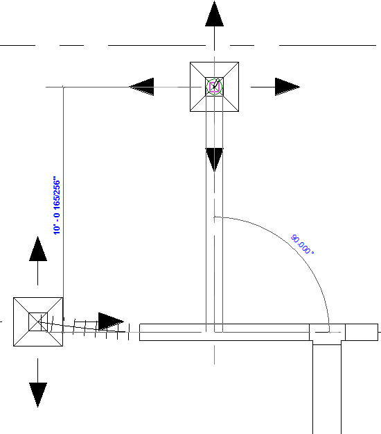
Drawing vertical duct from a horizontal duct run
- On the Options Bar, specify the Offset for the duct and draw a horizontal duct segment, click to specify an end point for the horizontal segment, then on the Options Bar, specify a different Offset, and click Apply.
A vertical segment is added from the connector on the horizontal segment to the specified Offset.
- Click Modify or continue the run.