Use the Hidden Line pane of the Mechanical Settings dialog to specify how ducts that cross each other (in separate planes) are presented in the model.
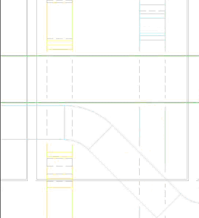
In two-line drawings, crossing duct and pipe segments are shown such that the lines representing the segment in the furthest plane are shown in a different style to indicate that they are hidden by, and not connected to the segment in the foreground as shown. Hidden Line parameters are only applied when the Hidden Line is selected as the visual style.
- Click Systems tab
 Mechanical Panel
 Mechanical Settings.
 - In the left panel of the Mechanical settings dialog, click Hidden Line.
- In the right panel, specify the following parameters for the line style and the width of that gap:
- Draw MEP Hidden Lines: when selected, duct or piping is drawn with the line style and gaps specified for hidden lines.
- Line Style: Click the Value column, and select a line style from the drop list that determines how the lines of a hidden segment display at the point where the segments cross.
- Inside Gap: specifies the gap for the lines that appear within a crossing segment. If Thin Lines is selected, the gap is not displayed.
- Outside Gap: specifies the gap for the lines that appear external to the crossing segments. If Thin Lines is selected, the gap is not displayed.
- Single Line: specifies the gap for the single hidden lines where segments cross.