Both plumbing fixtures must be assigned to a sanitary system, but because the flow in a sanitary system depends on gravity, the piping should be sloped.
The Generate Layout tools let you specify the layout and the slope for much of the sanitary system. However, some modifications, such as vents and traps, and connections between different building levels must be made manually. Begin by creating the sanitary system.
Layout Piping for the Sanitary system
- Select one or more plumbing fixtures in the plan view.
- Click Modify Plumbing Fixtures tab
 Create Systems panel
 (Piping).
- In the Create Piping System dialog, specify the following:
- System Type: the type of fixture selected in the view determines which System Type it can be assigned to. For a plumbing system, the default system types are Sanitary, Domestic Cold Water, Domestic Hot Water, and Other.
Note: You can also create custom System Types to handle other types of components and systems.
- System Name: uniquely identifies the system. Revit suggests a System Name or you can enter a name.
- System Type: the type of fixture selected in the view determines which System Type it can be assigned to. For a plumbing system, the default system types are Sanitary, Domestic Cold Water, Domestic Hot Water, and Other.
- Click OK.
The previously unassigned system is moved to the Piping folder in the System Browser.
- Open a 3D view showing the plumbing fixtures, and type the keyboard shortcut
w t to tile the views.

- In the plan view, select one of the plumbing fixtures in the sanitary system.
- Click Modify Piping Systems tabLayout panel
 (Generate Layout) or
 (Generate Placeholder).
- If more than one system has been created for the fixture, in the Select a System dialog, select the new sanitary system, and click OK.
The Generate Layout tab is activated.
Note: When creating sloped piping, be sure to have a valid drainage point in the system or use the Place Base command to establish a valid drainage point. - On the Modify Layout panel, click Place Base.
- On the Options Bar, click Settings.
- In the Pipe Conversion dialog, specify the type of pipe and the offset for the Main and Branch segments of sanitary piping.
For this example, the Main and Branch are set for a Pipe Type: PVC, and an Offset of -1' 6" (-450 mm), which places the piping below the level associated with the current level in the plan view.
Click OK. - On the Slope panel, select a value for Slope Value; for this example, 1/8" /12" (32 mm).
- Accept the default plumbing Solution Type: Network, and click
 or
or
 to cycle through the proposed routing solutions to select the one that best fits the plan. For more information about Solution Types, see Generate Layout.
- If necessary, click Modify, and reposition pipe segments to avoid obstructions.

- Click
 (Finish Layout) when you are satisfied with the routing of the piping for the system.
The piping is created according to the specifications in the Conversion Settings dialog and on the Options Bar.
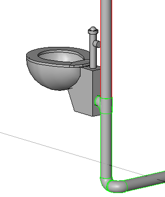
Note: Local building codes often require 45 degree junctions for waste plumbing. See Changing Routing Solutions to learn how to modify a 90 degree fitting. - Select the elbow connecting the vertical pipe to the sanitary main pipe from the back of the toilet, and click the plus sign above the elbow to upgrade the fitting to a tee.

- Select the floor plan view, select the tee fitting, and highlight the connector on the tee.
The lower connector is the first connector highlighted.
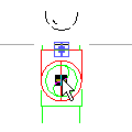 Note: The connector symbol may not be visible. Instead a highlighted square displays.Press Tab once to highlight the upper connector (a slightly larger highlighted square), right-click the connector, and click Draw Pipe.
- On the Properties palette, under Mechanical, select Vent for the system type.
- On the Options Bar, enter 8' 0" (250 cm) for Offset, click Apply, and click Modify.
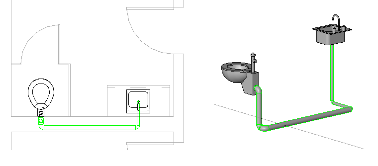
The Generate Layout tools let you define the layout for piping in the sanitary system.
You can create a vent by upgrading the pipe fitting, specifying the system type, and drawing a vertical segment to serve as the vent.